


Contributing Writer
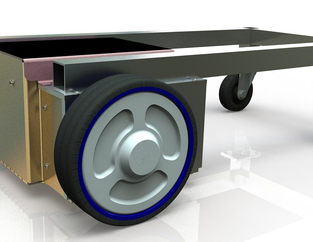
FIGURE 2. This is the concept design for a wheel cover. It fits in place, but the design is not suitable for manufacturing.
CAD’s ability to fill in the title blocks on drawings relies upon File Properties to convey product manufacturing information (PMI) from the model to the drawing.
Disclaimer: That statement is perhaps true only for a brand of mainstream 3D CAD and for the way in which its tools are being used in this demonstration.
File Properties are a feature of the Windows operating system. A software application like 3D CAD, or even a person with a mouse, might use the File Properties feature to embed useful information in the file.
Each File Property is given a name that makes sense to the application or end user. That name is used for both storing and retrieving a value—the embedded information. The value is usually a brief single sentence, a number, or a date.
For example, a Custom Property named LOCATION TOLERANCE might have the value BASIC (LOCATION) TOLERANCE ±0.016 UNLESS OTHERWISE NOTED. The title block would use the property named LOCATION TOLERANCE to retrieve the value and display it in the proper location on the title block. (As a side note, Mike Matusky writes about geometric dimensioning and tolerancing topics on TheFabricator.com.)
As presented in several of the 2022 episodes of this column, the labor data entry of the PMI employs some type of a user interface. We’ve been developing a Custom Properties Form (a screenshot is shown in Figure 1) as the user interface using tools built into a brand of mainstream 3D CAD. File Properties and Custom Properties are synonymous as used here.
When everything is working well with our template system, the Custom Properties form is used to quickly add PMI to a new component (part or assembly) as its design is refined.
Subsequently, as the 2D drawing (slddrw) for the 3D component is created, the title block’s fields (as examples, Description, Revision, Material, Finish, Tolerance, Author) are filled in.
The automatic title block works smoothly because both the component and the drawing have been set up to use an exactly named (perfectly spelled and capitalized) set of File Properties to retain the PMI.
The Custom Properties form speeds the data entry and eliminates the need to think about the names of File Properties that are being used. Only we form and template designers mess with property names. The user of the form just focuses on values and meaning. (That’s groaning intended as humor.)
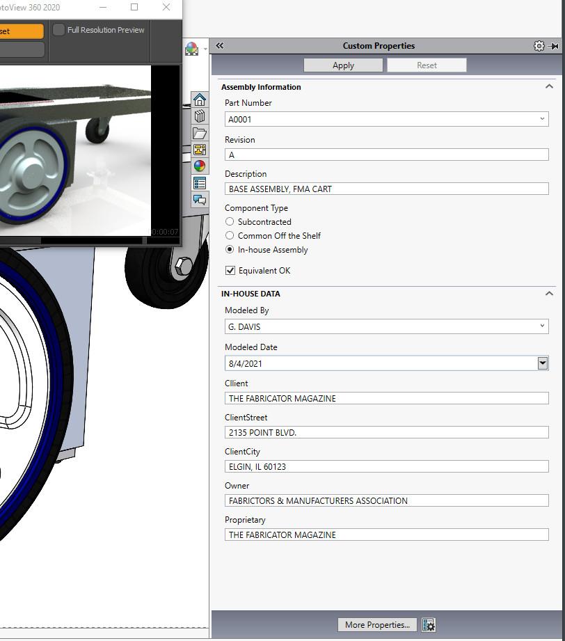
FIGURE 1. This Custom Properties form is used to enter product manufacturing information. It features radio buttons, selection lists, and strong hints about what data is to be entered.
Sometimes the data entry of PMI is painfully tedious, no matter how convenient the Custom Properties form. This is especially so if it becomes a repeated task because the PMI gets wiped out.
Buck it up, Bucky! There is a fairly easy way to back up the Custom Properties in a CAD file and to restore those to another (perhaps imported) CAD file.
A common design evolution is used for demonstration. At least, it has been a common design evolution for me in my practice recently. Here’s the scenario: As the design goal, the FMA Cart needs a decorative cover (see Figure 2). The decision is made to use an injection molding process for fabrication of the cover.
The initial design is completed with materials and textures for visualization. All PMI is entered, the 2D drawing (slddrw) is completed, and a PDF is released for fabrication. A STEP file is generated for distribution along with the PDF.
Here’s a side note: The STEP file is sent, as opposed to the native CAD file, because it is stripped of design history, which makes it hard to accidentally edit, and because our internal use of File Properties (for drawings and other documents) is also removed.
After importing and reviewing the concept design, the tooling shop makes appropriate design-for-manufacturing (DFM) decisions, redlines the PDF, and exports an improved STEP file showing the needed corrections. Perhaps changes might be made to draft angles, ejection points, gates, or vents. (Figure 3 shows the subtle improvement.)
When this improved STEP file is imported, it shows the corrected shape, but it lacks any of the PMI, materials, and textures. Accordingly, its 2D drawing (slddrw) is lacking needed information, and the drawing needs to be updated to reflect the redlined DFM suggestions.
There is a choice to be made. One could modify the native CAD to match the DFM suggestions, thus preserving PMI, material, and textures, or one could copy the PMI and paste it into the imported CAD model. A redo of the decal and appearance stuff might be needed if rendering or inertial studies are required.
The CAD system has a built-in, Windows-like user interface (see Figure 4) for editing Custom Properties. This good ol’ interface is table-oriented; rows and cells may be pretty much edited using your Excel skills. To select all of the property rows in the table, drag with left mouse button down and then CTRL-C to copy them to the clipboard.
Use the same good ol’ interface (Menu>File Properties>Custom tab) with the imported file open to paste the copied properties from the clipboard. Save your work early and often. The imported file now has inherited its Custom Properties and should work well with the 2D drawing’s (slddrw’s) title block.
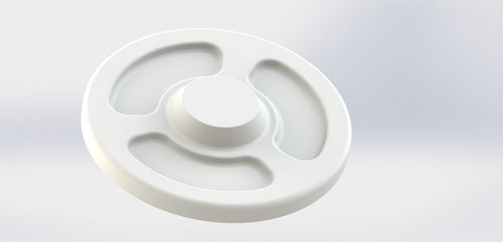
FIGURE 3. The imported STEP file shows change to the shape to improve the part’s manufacturability. With the addition of textures and colors, the model renders well. Sadly, it has been stripped of PMI by the import/export process.
But wait. What if slddrw is still opening the original sldprt, not the improved/imported sldprt? Oh, by the way, the imported STEP was saved to a file name different from the original sldprt to avoid burning bridges, as it were.
Use Replace Component to repair the views in the slddrw; it takes a few mouse clicks to set up but often is quicker than starting a new slddrw from scratch.
OK, but now the slddrw has a bunch of dangling dimensions. Is it better to delete them or try to drag them back into attachment? We’ll pretend the answer is a cliffhanger for the next column, but really, the answer is both.
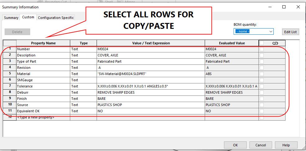
FIGURE 4. The good ol’ File Properties user interface is table-oriented. To copy all of the properties to the clipboard, select the rows and use CTRL-C. Then switch to the imported STEP file, open the same File>Properties dialog, and use CTRL-V to update the new file with old properties.


The Fabricator is North America's leading magazine for the metal forming and fabricating industry. The magazine delivers the news, technical articles, and case histories that enable fabricators to do their jobs more efficiently. The Fabricator has served the industry since 1970.
start your free subscription
Easily access valuable industry resources now with full access to the digital edition of The Fabricator.

Easily access valuable industry resources now with full access to the digital edition of The Welder.

Easily access valuable industry resources now with full access to the digital edition of The Tube and Pipe Journal.

Easily access valuable industry resources now with full access to the digital edition of The Fabricator en Español.
In this episode of The Fabricator Podcast, Caleb Chamberlain, co-founder and CEO of OSH Cut, discusses his company’s...


