


Contributing Writer
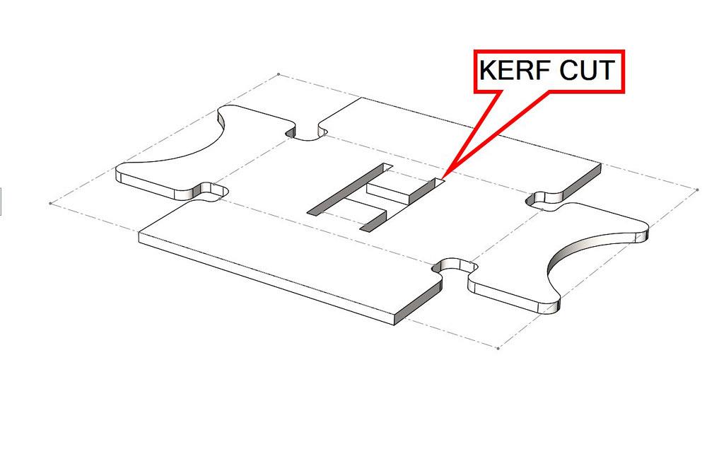
Figure 1a
The flat pattern requires prediction of how the material will behave as it is bent. Kerf is the air gap left behind by the cutting tool. Punching requires a kerf width that is equal to the material thickness.
A reader recently asked for guidance in using 3-D CAD for designing sheet metal parts. To summarize this month’s recommendation: Understand how the sheet metal gets bent.
We offer a few bending equipment details that might not be familiar to those outside the fab shop:
Folding machines, also known as folding brakes, box brakes, and pan brakes, clamp the sheet metal workpiece on a stationary bed and swing the skirt of the brake—like a leaf on a hinge—to create the bent flange. Folders are more common in the architectural, ornamental, and ducting trades. “Bending up and down, no flipping required,” The FABRICATOR, July 2008, has additional information on folding technology.
Here is a CAD tip: Check with the fab shop to verify that machinery is available to produce the intended design.
Regardless of the machinery used, sheet metal has characteristics during bending that will be evident in the final product:
A flat layout, shown in Figure 1a, is the prediction of what the finished part, shown in Figure 1b, looks like before it is bent. Designers of sheet metal parts should care greatly about their flat layouts. At the same time, designers should understand that fabricators will adjust the flat layout to satisfy immediate circumstances, such as available tooling, machinery, and material.
Flat layout planning on the part of the designer can lead to better design of kerf cuts when planning interior tabs and flanges. The designed width of the kerf cut is likely to dictate whether the part can be stamped, laser-cut, or punched/nibbled from the sheet stock.
Here’s a CAD tip: The default kerf width is equal to the material thickness. This tip is important for punched parts. Smaller kerf widths, as small as the cutting orifice, are practical for laser- cut or waterjet-cut parts.
An accurate flat layout helps with material planning and cost estimating. Material planning allows for the prediction of the economic order quantity (EOQ) as described in Part II of this series. An example nest of flat parts is shown in Figure 1c.
On one hand, flat layouts are usually a button-click in 3-D CAD—very easy. On the other hand, accurate flat layouts are more challenging to produce. The tooling used in the brake has a large impact on the way the material stretches as it is bent. Variations in the material thickness and speed of the machinery change how the workpiece will react with tooling.
Here’s another CAD tip: In the unusual situation where the accuracy of the flat layout is critical to the design and function of the product, the CAD jockey must be well-informed regarding the specific fabrication process.
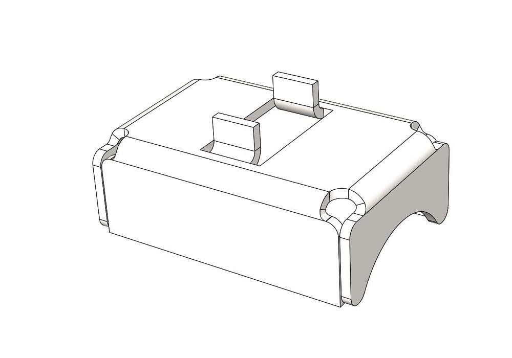
Figure 1b
This example part has interior tabs, overlapping corners, and bend relief cuts. Its flat pattern is shown in Figure 1a.
In the majority of projects, it is sufficient for the CAD jockey to simply verify that the design will unfold. Applying the same bend deduction/allowance as the fab shop is good practice but is not required for good design.
As good design practice, set the tolerances in the finished/folded design using your understanding of where variation is likely to occur as the workpiece goes through various manufacturing stages.
Each piece of equipment used—to cut or to bend, as examples—contributes variation in the workpiece. Flat parts coming off of lasers or nibblers are usually consistent within ±0.004 in. Precision brakes typically repeat within ±0.004 in.
As a general recommendation, ±0.005 in. runs right at the limit of precision flat sheet metal in a job shop environment. For bent sheet metal, variation in the raw material thickness increases the recommended precision to ±0.010 in. per bend.
“Sheet metal stretches when it bends” is an oversimplification. Upon close examination of the bends, we find that the sheet metal stretches on the outer surface and that the inside surface seems to shrink. “The basics of applying bend functions” (The FABRICATOR, November 2012) by Steve Benson explains it in detail.
If all of the inside depth measurements of the flanges are summed, then a bend allowance must be used to prestretch the flat stock so it shrinks into final size. Conversely, if all of the outside measurements are summed, then the bend deduction must be used to preshrink the flat stock. This is the traditional method used in the fab shop for calculating flat layouts.
A CAD jockey could, or probably should, use the fab shop’s calculation values so that the flat layout is ready for manufacturing. As mentioned in Part II, this is easily standardized in CAD by using a gauge table when setting up the base flange. The gauge table can cross-reference the fab shop’s bend deductions into K-factors for the 3-D CAD system.
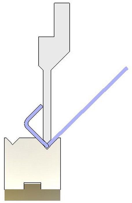
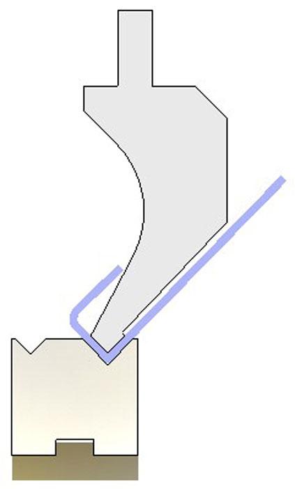
In the fab shop, the V-die width in the press brake limits the size of the flange that can be bent. During bending, the sheet metal must bridge fully across the V die (see Figure 2). The V die is usually selected to be 5x to 8x the workpiece thickness. Brittle materials may require V dies in the 8x to 12x range. “Finding the perfect die opening” (The FABRICATOR, February 2013) details how such tooling is selected.
If the V-die width is 5x material thickness, then roughly 6x material thickness will be required to safely bridge the die. The upper tool splits that in half, and as a result, 3x material thickness is the recommended minimum flange size for air bending on a press brake.
A smaller V results in creating a bend radius that more closely matches the upper tool’s radius. This is due to increasing the pressure of the tooling on the sheet stock. Wider dies make gentler bends because of mechanical advantage. Increased pressure also increases the mars on the workpiece. These appear as burnished and embossed lines that run parallel to the flange length.
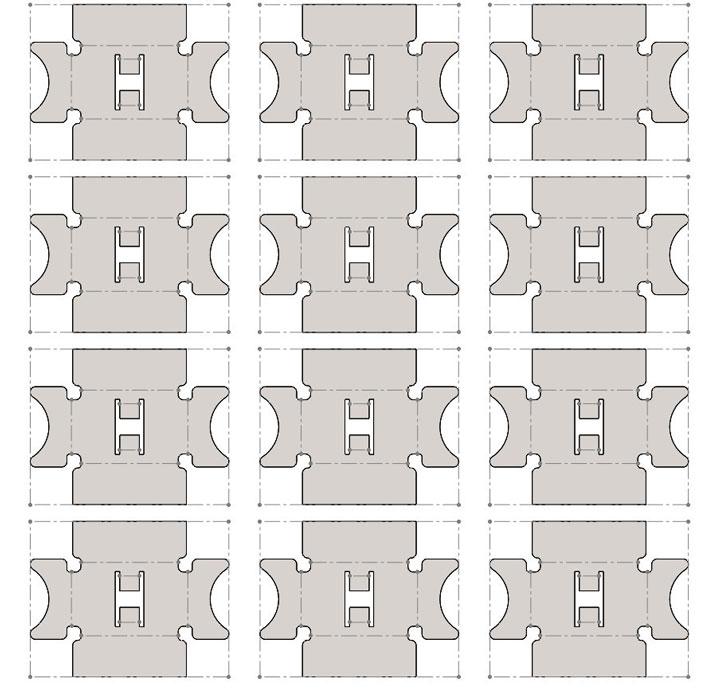
Figure 1c
The flat pattern is used for nesting several copies of the same part onto a blank sheet of raw material. This is useful for cost estimating and for predicting the economic order quantity.
While a general rule for minimum inside flange depth is 3x the workpiece thickness, a folding machine does not have this V-die tooling, so shorter flange depths can be formed with a folder as compared to an air-bending press brake.
Here’s a design for manufacturability (DFM) tip: Consult with your fab shop to verify that it has the capability to manufacture the desired bend radius.
The fab shop probably will adjust the tooling setup to compensate for variation in the flat workpiece. Any change to the tooling selection, such as V-die width or the top tool’s radius, changes the way that the flat workpiece shrinks/stretches.
If the 3-D design starts with the inside radius set to about the same value as the thickness, then the fab shop has many options in terms of tooling and setup. This could translate into less scrap and less time in production. That means money.
As a technique for making a flat blank form into an accurate finished product, selecting a wider V die allows an undersized workpiece to form up into a larger overall part. To some degree, a larger radius in the upper tool improves the strength of the final bend as well.
As the bend radius gets smaller, the strain in the workpiece increases. When the material’s fatigue point is exceeded, cracks form. Brittle metal, such as aluminum, generally requires a larger bend radius than ductile material like cold-rolled steel. For example, 6061-T6 aluminum is very difficult to bend. It requires an inside bend radius of at least 6x the material thickness. 5052-H32 aluminum bends in about the same way as mild steel. 3003-H14 is extremely ductile, almost like copper. Ductile material works great with small bend radii and short flange depths.
In summary, the 1x Thickness = Inside Radius Rule works for steel, stainless, and other ductile materials. Consult with the fab shop when incorporating a bend radius that is less than the material thickness in the design.
When two edge flanges intersect, a corner is formed. At the corner, the flange lengths can either overlap, underlap, or butt. The fab shop’s main concern with corners is the sheet metal’s memory. Overbending each flange is necessary to allow it tospring back to the correct unrestrained angle. This topic was covered in more detail in Part II of this series.
When it comes to two or more closely spaced bends, the design theme for manufacturing is extremely important. U-channels may be modeled in many ways: as part of the sketch for the base flange, a pair of edge flanges, or a miter flange.
In the fab shop, U-channels are created by a sequence of two bending operations. The first bend is almost always easy, but design limits do exist. The overall design is limited in maximum flange depth by the backgauge’s reach—29 in., for example—and is limited in flange length by the tooling bed and frame of the brake—72 in., for example.
The second bend in a U-channel has additional constraints. As this bend is completed, the first flange swings into position to complete the U. See Figures 3a and 3b. The frame of the brake may prevent that swing from completing. For small U-channels, the tooling itself may present the interference.
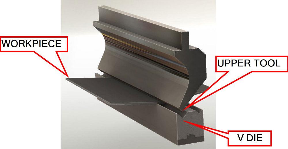
Figure 2
The workpiece must fully bridge across the V die as the upper tool creates the bend. V-die width of 6x the material means the shortest flange is 3x material thickness.
Here’s a DFM tip: It may be necessary to make the U out of an L and an I that are welded together.
During setup in the fab shop, profile templates of brake tooling can be used to visually select the upper punch. With a 1-to-1 drawing of the completed U-channel, the shop can position the tooling template to verify that access is sufficient to complete the second bend. Then the actual tooling can be loaded into the brake with confidence.
Similarly, in the CAD shop, models of brake tooling, please see Figure 2, can be used to evaluate the design for fabrication access. Access is a significant requirement; strength of the tooling matters as well.
The tonnage required to bend the part is equally important. Longer flange length and greater thickness call for increased tonnage. Increasing the bend radius with a wider V die helps to reduce the tonnage needed to complete the bend. If in doubt, consult with the fab shop regarding its capability.
A folding brake’s upper jaw limits the range of U-channel sizes that can be formed, as the first flange swings toward it. Narrow U-channels are routine on folding brakes. Press brakes have more difficulty forming closely spaced bends because of structural requirements of pressing rather than folding. Strength needed to complete the bend simply takes up space.
Gooseneck tooling is used in press brakes to form relatively narrow U-channels. However, the shape of this tooling is inherently weaker than a straight punch. Check with the fab shop regarding maximum material thickness and minimum U-channel sizes.
Gerald Davis uses CAD software to design and develop products for his clients at www.glddesigns.com. Please send your questions and comments to dand@thefabricator.com.


The Fabricator is North America's leading magazine for the metal forming and fabricating industry. The magazine delivers the news, technical articles, and case histories that enable fabricators to do their jobs more efficiently. The Fabricator has served the industry since 1970.
start your free subscription
Easily access valuable industry resources now with full access to the digital edition of The Fabricator.

Easily access valuable industry resources now with full access to the digital edition of The Welder.

Easily access valuable industry resources now with full access to the digital edition of The Tube and Pipe Journal.

Easily access valuable industry resources now with full access to the digital edition of The Fabricator en Español.
In this episode of The Fabricator Podcast, Caleb Chamberlain, co-founder and CEO of OSH Cut, discusses his company’s...


