


Bending large radii on the press brake
Questions about large radii and the effects of changing material
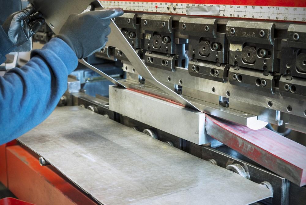
Press brake expert Steve Benson answers questions about bending large radii and the effects changing the material has on the bend angle, radius, and flat pattern development. Fertnig / iStock / Getty Images Plus
Question: We need to form a U-shape with two bends, each with a 1-in. radius in 0.0478-in.-thick mild steel (see Figure 1). The two sides of the U have an outside dimension of 18.048 in., and the dimension between the sides is 13.568 in. What round punch and die combination should we use?
Answer: This is a lot more difficult than it first appears. The reason involves the width and depth of the part. As far as which die to use, that depends a lot on the method of forming, though I’ll focus here on the one likely to give you the best results.
When you air form to a large inside radius-to-material thickness ratio, you will likely find you have a profound-radius bend relationship between the radius and the material thickness.
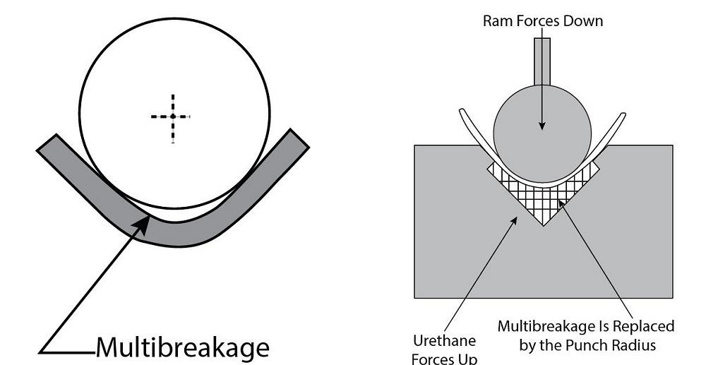
So that everyone is on the same page, a quick review is in order. We have two categories of bends that have large radius-to-material-thickness ratios—surface (or radius) bends and profound-radius bends. Here’s the difference between the two. As a bend radius gets larger relative to the material thickness, you will see an ever-increasing amount of springback. In a radius or surface bend, the inside bend radius is usually between 125% and 10 to 12 times the material thickness, depending on the material type. When forming radius bends, the punch nose remains in contact with the bend. At some point, though, springback effects cause the material to separate from the punch nose as bending angles pass 90 degrees. This phenomenon is known as multibreakage, and it’s a signature characteristic of profound-radius bends.
Generally, large-radius bends are all surface bends until the bending angle exceeds 90 degrees and the possibility of multibreakage arises. If the part radius is going to be smaller due to multibreakage, how do you correct it? You correct it by forming it into a urethane backup or pad. The urethane pad acts as a solid hydraulic and forces the part to follow the punch profile.
You can use a pad held in a retainer box or one shaped to fit into a V die. For instance, you might form material into a mid-range-durometer urethane (50 or 60 durometer) and a pad volume that’s 10 times the volume of the penetrating punch nose radius. Forming into a urethane pad will force the part up against the punch radius and produce a radius the way bottom bending does (see Figure 2). Also note that as the bend angle relaxes when released from pressure, the bend will spring back—and when the angle relaxes, so does its radius.
To account for springback, the punch nose radius needs to be slightly smaller than the required inside bend radius. To determine the correct punch nose radius, take the punch you wish to start with. Now, bend a piece of material. What angle did you need to overbend to (the bent-to angle) in order to achieve the required bend angle?
Divide that bent-to angle by the final bend angle, and you’ll calculate your springback factor: for example, 92/90 = 1.022222222. Multiply that value by the punch nose radius, and you’ll calculate the actual radius in the part after it’s released from pressure.
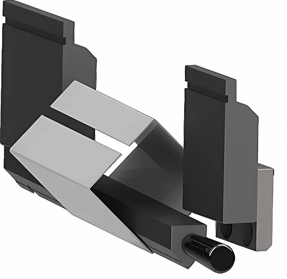
I am not sure about the bend length, but the flange depth and overall-dimension width won’t be easy to deal with. You could use a very deep gooseneck punch to allow clearance for your previously formed flange. Alternatively, you might need a tunnel or window punch. These have a “window” integrated into the punch body that would give you the clearance you need (see Figure 3).
New Material Changes Everything
Question: Say we start with A36 hot-rolled plate, bend it to 90 degrees, and end up with 2-in. leg lengths (2 × 2 in.). If we then use the same flat pattern DXF but form Grade 100 material instead, would we get the same 2-in. leg lengths? Would changes to the radius or other characteristics make the dimensions of the final product different? Do we need to change the flat pattern for different grades of material? We use the same punches and dies for both A36 and Grade 100, which means our tonnage goes up to form Grade 100.
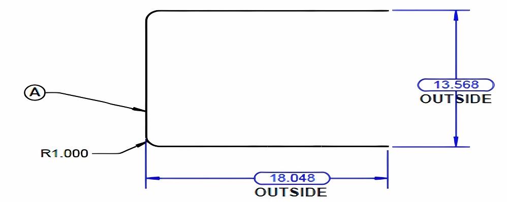
FIGURE 1. This U-shaped part made of 0.0478-in.-thick material looks simpler than it really is.
Answer: Yes, whenever you change the material properties, you change the results. The material tensile and yield strengths will tell you everything that you need to know. A36 has a minimum yield strength of 36,000 PSI and an ultimate tensile strength between 58,000 and 80,000 PSI. Compare that to Grade 100 with an ultimate tensile strength between 110,000 and 130,000 PSI and a minimum yield strength of 100,000 PSI. That’s a 177.7% increase in minimum yield strength and 37.5% increase in ultimate tensile strength.
I’m assuming the thickness of this sheet material remains consistent and the die width and punch radius remain constant. I’m also assuming the die opening is within reason—not too small or large for the material thickness—and the inside bend radius is neither sharp nor profound. Here is what will likely happen.
That A36 in thinner sheets will develop the inside bend radius of a percentage of the die width. For example, air forming a piece of 16-ga. A36 over a 0.472-in. die opening will give you an inside bend radius of about 0.075 in.
If you have been reading my column for any length of time, you will know about sharp bends. For those of you who are new, here’s the concept. If the punch radius is small enough and the tonnage gets high enough relative to the surface area of contact, then the material at some point will not be strong enough to resist the pressure, and the punch nose will pierce the surface and leave a crease in the center of the radius. The radius still “floats” during bending, though it will be a bit more of a parabolic shape as opposed to a true radius.
As the strength of the material increases, the floated radius air-forms as a larger percentage of the die opening. Higher-strength stock might form a radius that’s 25% to 28% of the die opening—if, that is, the punch nose isn’t too sharp and the bend radius is close to the material thickness (that is, close to a perfect, one-to-one relationship between the inside bend radius and material thickness).
If you use an even larger punch nose radius, the material will start to follow that punch radius rather than “float” in the die opening. A similar phenomenon can happen if you’re bending a little sharp with a narrow punch nose. The metal will conform to that punch nose radius, yet the force might not be quite high enough to pierce the center of the bend.
So, long story short, changing the material, or its properties, changes the way the metal forms. The same is true if you change your punch radius and, especially, your die opening. This can change everything and make an existing flat different, if not rendering it unusable. Most likely, you will have to change your flat pattern.
subscribe now

The Fabricator is North America's leading magazine for the metal forming and fabricating industry. The magazine delivers the news, technical articles, and case histories that enable fabricators to do their jobs more efficiently. The Fabricator has served the industry since 1970.
start your free subscriptionAbout the Author

About the Publication

- Stay connected from anywhere

Easily access valuable industry resources now with full access to the digital edition of The Fabricator.

Easily access valuable industry resources now with full access to the digital edition of The Welder.

Easily access valuable industry resources now with full access to the digital edition of The Tube and Pipe Journal.

Easily access valuable industry resources now with full access to the digital edition of The Fabricator en Español.
- Podcasting

In this episode of The Fabricator Podcast, Caleb Chamberlain, co-founder and CEO of OSH Cut, discusses his company’s...
- Trending Articles
1
Tips for creating sheet metal tubes with perforations

2
Are two heads better than one in fiber laser cutting?

3
Supporting the metal fabricating industry through FMA

4
JM Steel triples capacity for solar energy projects at Pennsylvania facility

5
Omco Solar opens second Alabama manufacturing facility
