


Dialing in the k-factor for bending sheet metal parts
The k-factor matters, but metal fabricators shouldn't overlook the tooling and bending method
zilber42 / iStock / Getty Images Plus
Question: Is there a simple way to dial in the k-factor using test parts made in the shop? For 18- and 20-ga. parts in 304 stainless steel and aluminized steel, I have my k-factor set to 0.42. We’ve designed parts with a 0.072-in. radius. But when you see an actual air-formed part, the radius is very close to 0.031 in. It gets a little larger as you increase the die opening, but it’s nowhere near the 0.072 in. We’re using punches with 0.008- and 0.030-in. radii and three or four different V dies.
I asked my operator to make some 0.049-in.-thick test parts, a simple bracket with 1-in. and 2-in. leg lengths. Whatever the legs measured, that’s what they are. Using a punch with a 0.008-in. nose radius and a 0.236-in. die opening, the 2-in. flange elongated to 2.024 in., and the 1-in. flange elongated to 1.045 in. We tested die widths up to 0.394 in., bending with a 0.030-in. punch radius, which gave us flange dimensions of 2.028 and 1.057 in. The larger the die we used, the more the legs elongated.
I do care somewhat about the inside bend radius of the finished part, but I really want the dimensions of the flanges to be correct. So, what do I need to do to dial in the k-factor and inside bend radius? I’d like to have one k-factor and one “ideal” bend radius to design my parts.
Answer: The first thing that I would recommend is to review August’s Bending Basics column on k-factors. For now, a quick review is in order before continuing with your question.
First, what exactly is the k-factor? It’s a multiplier that represents the neutral axis’s final position after bending (see Figures 1 and 2). The neutral axis is a theoretical area within the bend where the material is neither expanded nor compressed. Before bending, the neutral axis starts at 50% of the material thickness, then moves inward during the bending cycle.
We incorporate the k-factor into our formula for the bend allowance (BA), which gives us the arc length of the shifted neutral axis after bending. To calculate an accurate BA, you need to know the inside bend radius your operators are actually achieving, which depends on the tools and bending method they’re using. If they’re air forming, the inside bend radius changes with the die width. Assuming you’re using a die that’s wide enough for the material grade and thickness (a die width six to eight times material thickness is typical, though it’s material-dependent), you can estimate the resulting radius with the following formula. Note that, as you’ve done, test bending is the best way to dial in what your inside radius will actually be. The below just gives a rough estimate to use as a starting point.
Inside Bend Radius for 60-KSI Cold-Rolled Steel = Die Width × 0.16
The percentage varies with the material and tensile strength. Say we need to work with 120-KSI material. That’s double the 60 KSI of our baseline material; hence, this 120-KSI sheet will air-form a radius that’s about double that of cold-rolled steel—or 32% of the die opening (16% × 2).
Back to the BA, the formula I cite, which comes from “Machinery’s Handbook,” is just one of many the industry uses:
BA = [(0.017453 × Inside Bend Radius) + (0.0078 × Material Thickness)] × Outside Bend Angle
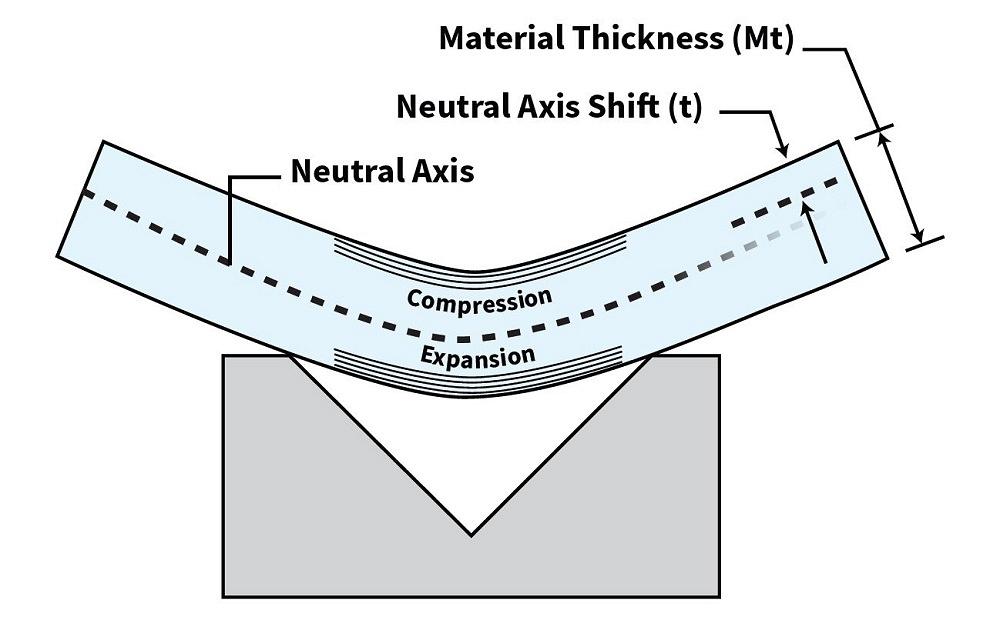
FIGURE 1. The k-factor, expressed as t/Mt, is a ratio that describes the neutral axis’s shift inward during bending.
Note the last variable—the outside bend angle, as measured from the outside of the bend (see Figure 2). The BA never uses the inside bend angle.
So, now you have a formula for the BA—but where’s the k-factor? It’s hiding in that 0.0078 value, which is π/180 × k-factor. To arrive at 0.0078, the equation uses a k-factor of 0.4468, a commonly used factor that’s the default for many CAD systems.
To dial in your bend calculations, you first need to determine whether you go with the default k-factor value of 0.4468, calculate a custom k-factor, or reverse-engineer it based on some test bends. For more on this, check out the August column, archived online.
Once you have your k-factor, you can then calculate your dialed-in BA with the following expanded formula, then calculate your outside setback (OSSB) and bend deduction (BD):
BA = {(0.017453 × Inside Bend Radius) + [( π/180 × k-factor) × Material Thickness]} × Outside Bend Angle
OSSB = [Tan (Bend Angle/2)] × (Material Thickness + Inside Bend Radius)
BD = (OSSB × 2) – BA
You can use either the BA or BD to calculate the flat blank size. Either will get you to the same answer, as shown in Figure 3. And as that figure shows, the BA and BD are not the same.
Wider Die, Larger Radius, Different Elongation
I ran the numbers you sent me through a spreadsheet calculator, and I found that your measured part values for both BA and BD matched mine. Assuming your test bracket’s total outside dimension needs to equal 3.000 in., you’ll need to subtract your BD of 0.076 in. from the flat blank dimension. With that, a flat blank dimension of 2.924 in. air formed over a die opening of 0.236 in. should elongate to that 3-in. outside dimension.
Bringing this full circle, a k-factor is not a BD or a BA but is a factor in creating a value for both. Depending on how you create your flats, you must either add the BA or subtract the BD. Again, see my August column for a more in-depth explanation.
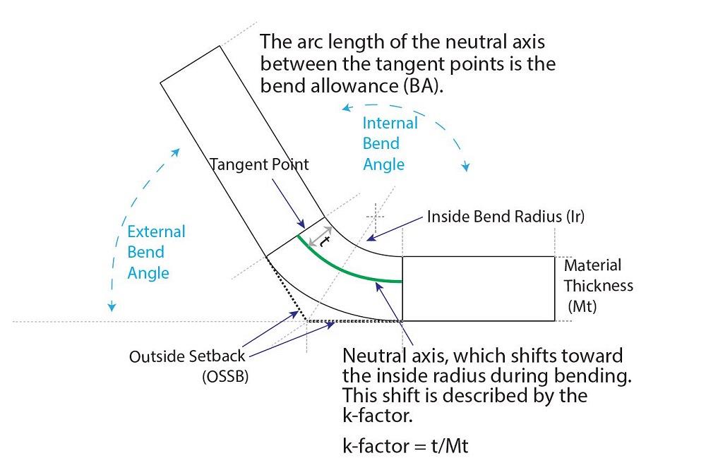
FIGURE 2. The k-factor describes the neutral axis’s shift inward during bending. That shift causes the metal to elongate, which we accommodate for in our bend calculations.
Not Just About the K-Factor
I believe the issues you are having are twofold: the basic use of the terminology and the applications of them. As a starting point, make sure everyone understands what common bending terms mean. A k-factor is not a bend allowance and a bend allowance isn’t a bend deduction. Sadly, these terms are commonly used interchangeably, and the values are applied incorrectly.
Also, when you air form with a larger die, you achieve a larger inside bend radius. The greater the radius, the greater the amount of elongation will be seen in the formed part.
As I’ve noted in previous columns, the k-factor is just one piece of a larger puzzle. Even if you do dial in your k-factor, variations in material thickness, grain direction, hardness, and a host of other variables can influence bending accuracy.
For instance, you mentioned some of your punches have a nose radius of just 0.008 in. That’s likely to give you a sharp bend, forming a crease along the bend line and giving you inconsistent results. Ideally, your punch should be slightly less than your floated air-formed radius. In air forming, a sharp bend can be detrimental to the project by amplifying the effects of any material variations, including material thickness and tensile strength.
Know that, no matter how well your k-factors are dialed in, when the inside bend radius changes, your bend calculations and flat blank size changes. As you’ve shown with your test bends, using a different die width when air forming changes that inside bend radius and, ultimately, the amount the sheet metal elongates. If operators just choose a tool that happens to be available, variations will be unavoidable.
You can go to great lengths calculating your k-factors to the nth degree. However, if your calculations don’t consider the bending methods and tooling your operators use, inconsistencies will continue unabated in the forming department.
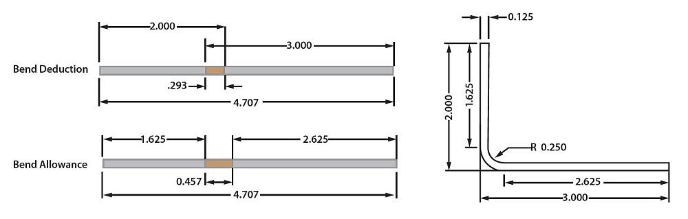
FIGURE 3. For this bend, a bend allowance (BA) of 0.457 in. is added to the two legs to create the proper blank size (1.625 + 2.625 + 0.457 = 4.707), which should elongate to a total outside dimension of 5.000 in. after bending. Alternatively, a bend deduction (BD) of 0.293 in. is subtracted from the desired outside dimension of the formed part (5.000 - 0.293), which results in the same 4.707-in. blank size.
subscribe now

The Fabricator is North America's leading magazine for the metal forming and fabricating industry. The magazine delivers the news, technical articles, and case histories that enable fabricators to do their jobs more efficiently. The Fabricator has served the industry since 1970.
start your free subscriptionAbout the Author

About the Publication

- Stay connected from anywhere

Easily access valuable industry resources now with full access to the digital edition of The Fabricator.

Easily access valuable industry resources now with full access to the digital edition of The Welder.

Easily access valuable industry resources now with full access to the digital edition of The Tube and Pipe Journal.

Easily access valuable industry resources now with full access to the digital edition of The Fabricator en Español.
- Podcasting

In this episode of The Fabricator Podcast, Caleb Chamberlain, co-founder and CEO of OSH Cut, discusses his company’s...
- Trending Articles
1
Tips for creating sheet metal tubes with perforations

2
Are two heads better than one in fiber laser cutting?

3
Supporting the metal fabricating industry through FMA

4
JM Steel triples capacity for solar energy projects at Pennsylvania facility

5
Omco Solar opens second Alabama manufacturing facility
