


Predicting the radius without test bending on the press brake
Why the 20% rule isn’t perfect for all metal fabrication shops
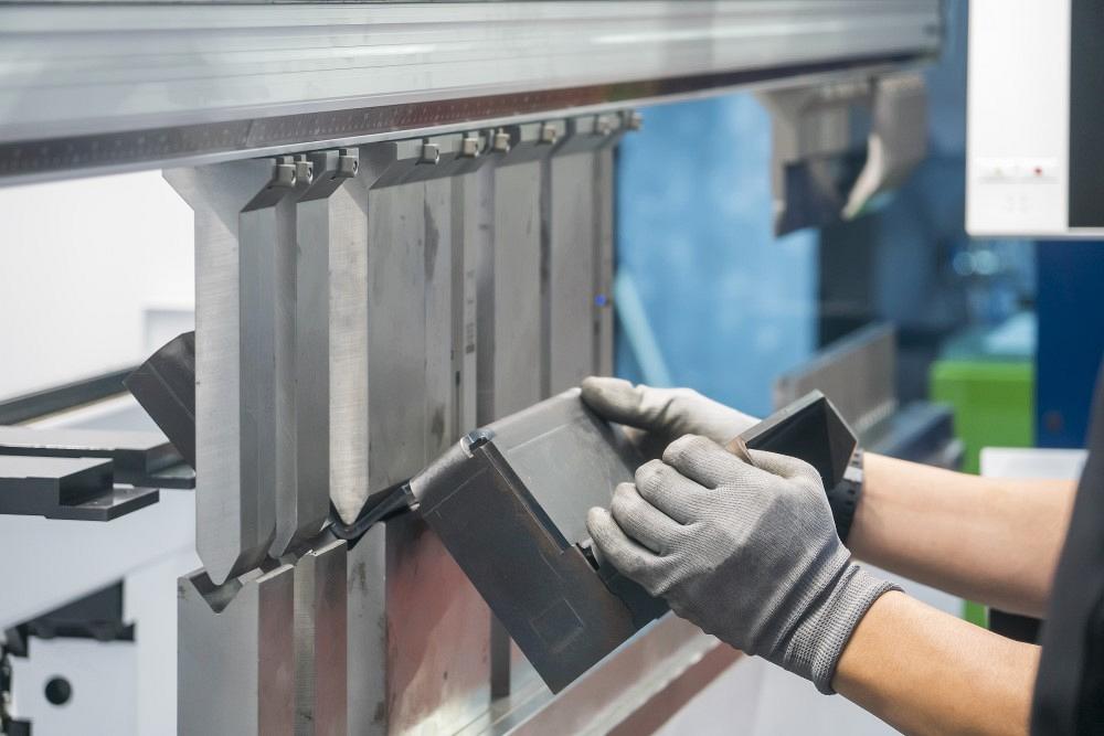
The 20% rule can estimate the air-formed radius a press brake operator is likely to achieve, yet it remains imperfect. Data based on empirical evidence—test bends—can help most bending departments in metal fabrication shop. Phuchit / iStock / Getty Images Plus
Question: We bend a lot of stainless, mostly 11-ga., 7-ga., 0.25-in.-thick 300 series stainless. I was recently tasked with creating bend tables for SolidWorks, but unfortunately, I had to do so without coupon data. I began with the 20% rule, which you’ve written about at length. (Stainless forms an inside radius that’s 20% to 22% of the die width, 15% to 17% with 60-KSI mild steel). The rule seems to hold up for one material we have. Forming a grade of 0.375-in.-thick stainless over a 4-in. V die gives us a 0.750-in. bend radius.
So, I generated all our bend deduction tables using the 20% rule (21% for stainless), and our parts are now starting to hit the shop floor. But it appears that the 20% rule hasn’t held up too well there.
Forming 0.25-in. plate over a 2-in. V die gave us a radius of 0.420 in., or just 60% of our expected radius per the 20% rule. When we bent 7-ga. stainless over a 1.5-in. V die, we formed a radius of 0.315 in.—again, just 60% of the value we expected. When we bent 11-ga. stainless over a 1-in. V die, we achieved a 0.21-in. radius, or 74% of the expected value. Why did the 20% rule not hold up in our case?
Answer: To start, let’s review how air bending actually forms the inside bend radius. The punch forces the metal into a die, but unlike bottoming or coining, the punch does not bottom out in the die. The resulting bend radius is determined by a percentage of the die opening and the resilience, strength, and thickness of the material—and as you’ve discovered, it doesn’t always abide by rules of thumb.
When you air form a piece of sheet metal, the bend radius is not determined solely by the punch nose radius. Rather, the radius is a function of the die width. The punch doesn’t force the metal completely into the die, allowing it to spring back slightly after forming.
This relieving of the inside bend radius is known as a springback factor (Sf), and it can be calculated by dividing the outside bending angle—or the overbent angle that compensates for springback—and the bent angle, or the angle of the bend when it is released from pressure (see Figure 1).
For example, I might form to a bend angle of 92 degrees to achieve a 90-degree final bent angle. To determine Sf, you divide the bending angle by the bent angle:
Sf = Bending Angle/Bent Angle
Sf = 92/90 = 1.022
That value is multiplied by the original inside bend radius. Let’s say that your expected radius is 0.062 in.:
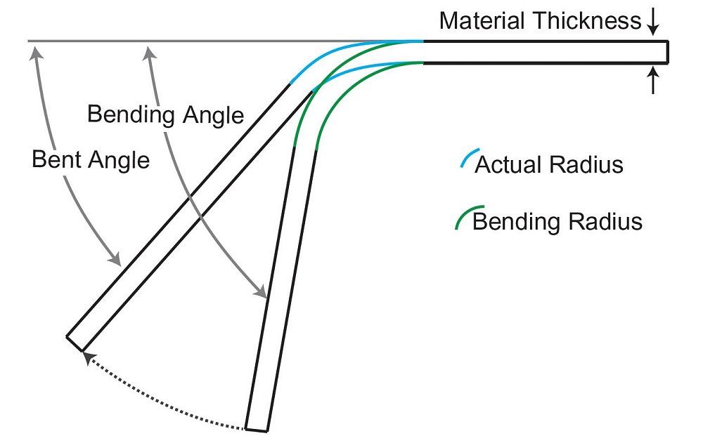
FIGURE 1. You form to the bending angle, after which the material springs back to its final bent angle
0.062 × 1.022 = 0.064 in.
In this case, 0.064 in. would be your working radius under perfect conditions and the value used to calculate your bend allowance and bend deduction.
The angular spread was 2 degrees, but it is not just 2 degrees. You must use the angles that are in play. Imagine you have two bends—one with an outside bending angle of 137 degrees and a bent angle of 135 degrees; another with an outside bending angle of 47 degrees and a bent angle of 45 degrees. Both have 2 degrees of springback, but they have different springback factors:
Sf = 137/135 = 1.014814
Sf = 47/45 = 1.0444444
Factors That Change the Radius
The bend radius in air forming is usually based on a percentage of the die opening, depending on the material’s properties. The bend radius can change for several reasons, even if you’re working with a consistent thickness and material type. One reason is, again, springback. Different die openings will result in different amounts of springback, which in turn affects the final bend radius. The metal’s elasticity allows it to spring back, which will be more or less pronounced based on the relationship between the punch and die dimensions.
Another reason the radius changes has to do with the material grain structure and internal stresses. This can alter the radius if the die opening changes.
When you increase the thickness of the same type of metal but keep the die size consistent, forming behavior changes. First, thicker metal has less springback because it’s stiffer and less elastic. It retains the deformation shape more than thinner metal.
Thicker material also increases your minimum inside bend radius to prevent cracking. Also, thicker material requires greater force to bend, which can lead to more pronounced deformation along the punch nose.
Meanwhile, if you decrease the die opening while maintaining a consistent material thickness, you increase the variations in bend angle, increase the tonnage requirements, and reduce the 20% rule’s accuracy.
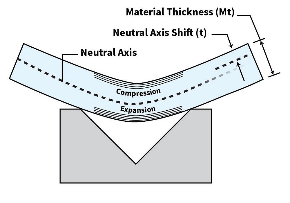
FIGURE 2. The k-factor, expressed as t/Mt, is the ratio that describes the neutral axis’s inward shift during bending.
If the material is thick enough, the inside bend radius will begin to conform to the shape of the punch nose rather than floating as a percentage of the die opening. This happens for several reasons, one of them being the increased stiffness of thicker material. This makes it harder for the material to be shaped by anything other than the punch nose. As the material gets thicker, the influence of the die on the bend radius decreases. Also, thicker material has less elasticity, so it doesn’t “bounce back” as much and the radius becomes more defined by the punch profile.
So, what does this all mean? In essence, the bending radius in air forming is a dynamic relationship between material properties, thickness, die opening, and punch shape. With increased material thickness, this relationship changes, and the punch nose starts to play a more significant role in determining the bend radius, reducing the variability (or floating) of the radius relative to the die opening.
Predicting the exact point at which the bend radius transitions from floating in the die space to conforming to the punch nose involves a complex interplay of factors, including material properties, tooling geometry, and processing conditions. As with everything else in metal bending, you are at the mercy of the material.
There isn’t a simple equation that applies universally, and the 20% rule is never an absolute. To develop a more predictive equation, you need to dig deeper into the material properties: its Young’s modulus, yield strength, and tensile strength, which determine how the material behaves under stress and its tendency to spring back. This data can easily be found on the internet.
Tool geometry also plays a role. The dimensions of the punch and die, including the punch nose radius and the die width, are critical. The relationship between the punch nose radius and the material thickness influences whether the material will or won’t conform to the punch nose. It’s also the reason why we always try to get a die opening as close to perfect as possible geometrically.
Finally, you need to know the k-factor, a ratio that describes the neutral axis shift within the material thickness during bending (see Figure 2). It’s critical for predicting the bend allowance and, thereby, giving you an accurate bend deduction. The k-factor can change with the material type, thickness, and strength.
The Observable Approach
You might want to collect data on how different materials with varying thicknesses behave in specific tooling setups. This data can then be placed in a table for later use or into your CAD software that uses these empirical specifics. This is time consuming, but it can be very accurate if, and I stress if, your material comes from the same mill or service center. If you obtain your material from several different sources, the data may not work out quite as well, even if you’re working with the same material type and gauge.
You could develop a predictive formula by, for instance, incorporating some coefficients and correction factors based on observed data. This can include the percentage of the die width that influences the radius, material thickness variation, material grain (anisotropic or isotropic), and other material properties.
Theoretical formulas must often be calibrated with actual data to provide accurate predictions due to the complexity and variability of the factors involved. This basically means that no matter how hard you try and how deep you are willing to go, predicting the inside bend radius is always going to boil down to a rule of thumb with extenuating circumstances. But at least now you know what is going on, even if predicting the results without empirical data will always be elusive.
subscribe now

The Fabricator is North America's leading magazine for the metal forming and fabricating industry. The magazine delivers the news, technical articles, and case histories that enable fabricators to do their jobs more efficiently. The Fabricator has served the industry since 1970.
start your free subscriptionAbout the Author

About the Publication

- Stay connected from anywhere

Easily access valuable industry resources now with full access to the digital edition of The Fabricator.

Easily access valuable industry resources now with full access to the digital edition of The Welder.

Easily access valuable industry resources now with full access to the digital edition of The Tube and Pipe Journal.

Easily access valuable industry resources now with full access to the digital edition of The Fabricator en Español.
- Podcasting

In this episode of The Fabricator Podcast, Caleb Chamberlain, co-founder and CEO of OSH Cut, discusses his company’s...


