


Tool choice for air bending on the press brake: Keep it consistent
Answering the gamut of readers’ metal forming questions
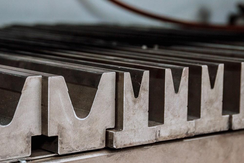
ZhakYaroslavPhoto / iStock / Getty Images Plus
Question: We are trying to set up our press brake station so we can begin making parts in-house. We have a simple 0.125-in.-thick aluminum test part, designed in CAD assuming a 0.41 k-factor. How would we set up our press brake station to complete this task? We’re having trouble holding the flange height with the overall length with any consistency. Would you use a setback from the 1.138-in. bend line to locate the backgauge? If so, how much?
Importance of Tooling Consistency
Answer: This is a very simple part, even if you are working with very tight tolerances (see Figure 1). Your k-factor should be fine for calculating the amount of elongation, whether that is the bend deduction (BD) or bend allowance (BA). Because you have consistency issues with these parts, I assume you are air forming them.
On that note, I would also think that your operators pick the tooling they use to form these parts. That being the case, the 1.138-in. dimension to the bend line will not always be valid as the die width greatly affects the inside bend radius. As you most likely know, if you alter the inside bend radius, you change the BA and BD, and your parts won’t be as accurate or repeatable as they could be.
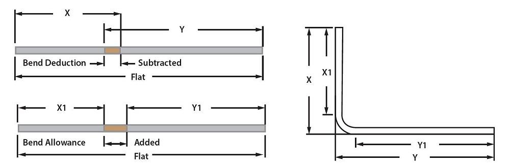
To make these parts consistently over time, you need to determine the amount of elongation for a single bend, either by calculating that value or physically bending a part and measuring it. To account for elongation, you can use either the BD or BA. Figure 2 shows you how they’re used to develop your flat blank. If you prefer to use the BA, you first need to calculate it and then add that value to the Y1 and X1 dimensions shown in the figure. Either method should get you to the same place.
When you do this, note the die opening and punch nose radius, as you will be using those tools every time, regardless of who is building the parts. Check the resulting inside radius of the bend, note it, and always make sure you are achieving that radius at the start of every part run. You’ll also use this radius value to calculate the BA and, ultimately, your BD.
Also note that the 1.138-in. bend-line dimension in your drawing might or might not be correct. To locate the bend line that will give you the flange height you need, you will either need to subtract one-half of the BD from the 1.250-in. flange dimension or add one-half of the BA from the inside dimension of the 1.250-in. flange. Doing this will locate the bend line. This number will also be the direct value you would put in the controller for the backgauge.
The big trick to consistently getting it all to work is using the same tooling. This will produce the correct inside bend radius, BA, and BD; and the flat dimension should always be right on the money.
What About Wooden Tools?
Question: I recently formed parts on 10-ga. hot-rolled pickled and oiled material for a water tank for a half-scale steam traction engine—essentially a riveted tank made of six mostly flat parts. They all have end flanges, and the top has an 8-in. offset radius transitioning into a 1.25-in. bend at each side. The large radius was press-formed using simple wooden tooling. I have further work for this project that would probably be best to roll, but I don’t have slip rolls or ready access to a set. Could these be press-formed with simple wooden tooling? Should this be an option, I’m unsure how to figure out the tool’s radius to produce a final radius of 7.5 in. for a 180-degree bend that would account for springback, other than by trial and error.
Answer: I would say that making a wooden punch would be OK with the large radius; a smaller punch radius would not work due to the concentration of force at the punch nose. Make your punch from nice hardwood—oak, for example. Softwoods like pine or poplar would not have much life in them. I would also recommend that you affix a thin piece of stainless steel sheet to the working surface of the radius. If that is not possible, coat the punch with epoxy resin. You will want to shape the punch radius slightly smaller than the required inside radius you are trying to achieve, as the radius will relax some when released from pressure.
Finally, for the die, I highly recommend using a urethane pad with a medium- to low-durometer rating, perhaps a 50 or 60 on the Shore D scale. You will also need a pad volume of 10 times that of the penetrating punch and material.
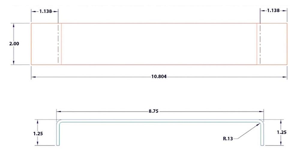
FIGURE 1. This part is simple to bend, even if you’re working with tight tolerances—as long as all operators use the same setup parameters, punch radius tip, and die opening.
Also, remember that even under the best conditions, a 180-degree bend will not be easy and may require you to bump form, taking several smaller hits to create the larger inside bend radius. When the tool is mounted into the press, the bottom edge of the punch radius should be parallel to the urethane pad and part.
Which Tool Is Best?
Question: We’re new to sheet metal bending, and we’re looking to form a 90-degree bend in aluminum. In one of your articles, you mentioned a 90-degree V die with an 88-degree punch. Does this work best, assuming 2 degrees of springback? We typically process only thin sheets. A few designs are 0.375 in. thick, but I believe we shop those out.
Answer: The tool combination you mentioned references a bottom-bending operation, and it wouldn’t be the best choice for air bending. If you are air forming a lighter-gauge aluminum sheet, I recommend using an appropriately sized 88-degree die and a smaller punch angle with enough angular clearance to compensate for springback.
You might even want to consider air forming with an acute angle punch and die, 28 and 30 degrees, respectively—that is, if your flange lengths are large enough to catch the far side of the die without slipping into the working area of the die.
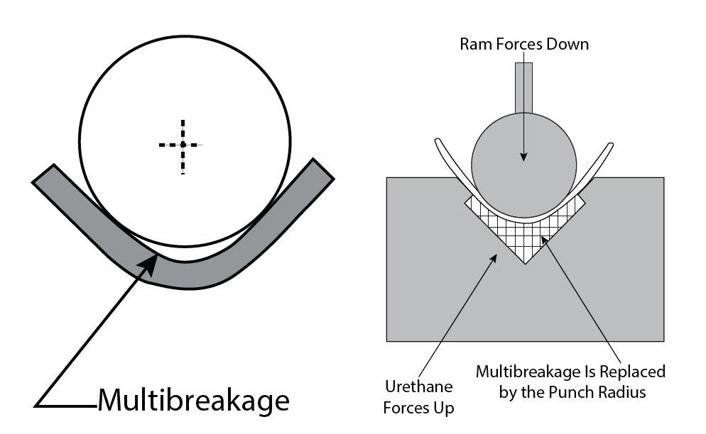
For the 0.375-in. material, you will look for a larger relieved die with the width appropriate for the desired inside bend radius. The punch angle is important here, but if you expect or encounter a great deal of springback, you will have to deal with multibreakage, or the separation of the material being formed from the nose of the punch. If you do, you will want to have a urethane pad or some high-pressure water hose available to place into the die space to force the material back against the punch (see Figure 3).
Tackling a Bending Challenge: 6061-T6 Aluminum
Question: I’m trying to form 0.5-in.-thick 6061-T6 aluminum. My piece is 24 in. by 48 in. and is supported on the corners. The pressure exerted on the center is a maximum of 2,500 lbs. Will the material bend?
Answer: Maybe. It would depend, in part, on the outside bend angle. If the outside angle is less than 80 to 85 degrees, you have a good chance at bending it. But as you get closer and past 90 degrees, you will need to anneal first.
It should form OK if you take an oxyacetylene torch with a rosebud tip and go back and forth down the bend line until the entire length is hot. As for the temper range required, I would consult with the mill.
There are a couple of things to remember if you anneal this way. First, aluminum does not change color when it is hot, so be careful not to get burned. Second, because the aluminum oxide on the material surface has a higher melting temperature, aluminum melts from the inside out. You could blow a hole through the material and never see it coming.
The best advice I can give, and assuming your cost structure allows, is to purchase the material you will use in an annealed state and then have it tempered to the necessary specifications after the forming is complete. This ensures you can form it and minimizes stress on your equipment and tooling. It also sounds like your machine might be pressure-challenged for the task, but again, that would depend on factors like the length of the bend and the width of the die.
subscribe now

The Fabricator is North America's leading magazine for the metal forming and fabricating industry. The magazine delivers the news, technical articles, and case histories that enable fabricators to do their jobs more efficiently. The Fabricator has served the industry since 1970.
start your free subscriptionAbout the Author

About the Publication

- Stay connected from anywhere

Easily access valuable industry resources now with full access to the digital edition of The Fabricator.

Easily access valuable industry resources now with full access to the digital edition of The Welder.

Easily access valuable industry resources now with full access to the digital edition of The Tube and Pipe Journal.

Easily access valuable industry resources now with full access to the digital edition of The Fabricator en Español.
- Podcasting

In this episode of The Fabricator Podcast, Caleb Chamberlain, co-founder and CEO of OSH Cut, discusses his company’s...


