


Contributing Writer
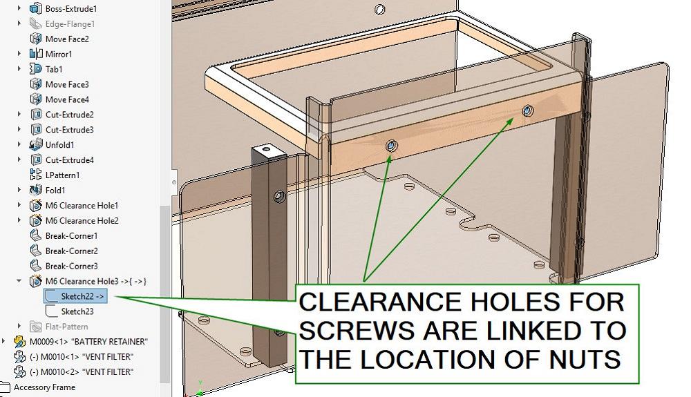
FIGURE 1. As an example of parametric linkage between components in an assembly, the Hole Wizard is used to create a pattern of clearance holes for screws. Each of the clearance holes has a concentric relation with the hole for corresponding captive fasteners.
One of the joys of mainstream 3D CAD is the ability to control what changes and what remains the same as the model evolves.
As an example, holes for fasteners can maintain desired alignment while other features change around them. Set-and-forget linkage allows you to do it right, do it once, and move onto the next thing.
There are more than a few methods of creating links. This discussion contrasts assemblies with multibody or derived parts.
Figure 1 demonstrates sketch relationships (links) that span components in an assembly. Here, a sheet metal cover’s clearance holes for screws are modeled using the Hole Wizard tool. The center locations for the pattern of holes have concentric relationships with the holes for the (threaded) captive fasteners in the frame.
Figure 2 shows the resulting cover and screws. The Hole Wizard creates a pattern that is useful for creating a pattern of fasteners. The advantage is less mating and more automatic modeling. Only the seed component needs to be constrained with mates. The patterned components follow what the Hole Wizard did.
CAD prognostication: Even when only two screws are in the pattern, someday it might become three, or even four. Solution: The Hole Wizard’s pattern is easy to edit and easier than mating parts.
If modeling reality is important, assemblies might be the best choice. Figure 3 shows an assembly of components. From the Windows perspective, this assembly is a file, and each of its unique components resides in another file. As parametric links are established, the filenames and locations of the files literally become part of the link. In other words, parametric links can be damaged by accidentally renaming, moving, or deleting a file. But there’s good news too.
The components in an assembly can be mated to simulate motion—in other words, to be mouse-draggable kinematic mechanisms. Although marvelous as a CAD technique, because of the overhead of Windows file operations (and the danger of moving or renaming a file without maintaining the parametric links), CAD assemblies are not always a panacea for modeling real assemblies.
An alternative CAD technique to assemblies that might address the clutter of filenames is the multibody part. A multibody part resides in a single Windows file. That’s possibly an advantage over an assembly.
Figure 4 shows a caster as a single multibody part. We note that the links between features for the multiple bodies reside in a single Windows file. The motive for using bodies (instead of a merged body) is that bodies can be positioned (to simulate swivel or rotation, perhaps).
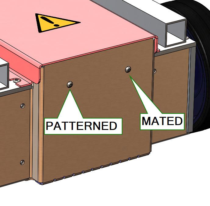
FIGURE 2. The Hole Wizard creates a useful pattern of holes. Mate the screw at the seed location and create a component pattern. All locations will populate. No additional mating is required.
Goals for collaboration might also affect the choice of CAD technique (using an assembly as opposed to a multibody part). Each component in an assembly can be owned and edited independently by a team of CAD jockeys.
Collaboration requires that no conflict exists with the distribution of modified files and the ownership of the assembly file itself. From personal experience, collaboration without the use of a document vault is risky and slow, but technically possible.
The size (surface count) of the project might present constraints on the best CAD technique to use. Some projects are so large that they cannot be loaded into memory all at once. Thus, some common frame of reference must be used to substitute for seeing it all at once.
Fortunately, parts can be inserted into parts. For the common frame of reference, create a part that contains nothing but planes and perhaps other lightweight (computer-friendly) reference geometry.
Insert that frame-of-reference part into each component (whether it be a part or an assembly), so all collaborators use the same frame of reference. If something in that parent-part’s geometry changes, then all of the children-parts with links to that parent update during their next rebuild.
Regardless of size, the project’s security requirements might benefit from using the frame-of-reference-part trick. It allows each collaborator to work in isolation, perhaps even unaware of other collaborators. Only those with proper credentials see the entire project.
Regardless of complexity, the use of a multibody parent model is a powerful parametric modeling technique, not just because of the convenience of visualizing and controlling change, but because the child-bodies can be saved as parts that maintain their link to their multibody creator. In other words, they inherit their starting point.
Parts derived from bodies may be further embellished with design features. The idea is that such embellishments have no relation to sibling components in the multibody. Otherwise, the embellishment would have occurred in the parent/multibody model.
Whether you are the entire team or merely a team member, techniques such as frame-of-reference parts within parts, parts derived from bodies, and components assembled in assemblies are crystal clear only to the mind that set them up. The goals of the CAD hierarchy should be anticipated by others if they are to preserve the desired chain of consequences.
CAD policy also can address the progress of the model from invention to production. The desired chain of consequences in the CAD hierarchy is certain to change. The blessings of set-and-forget parametric links are manifest as the design is changing.
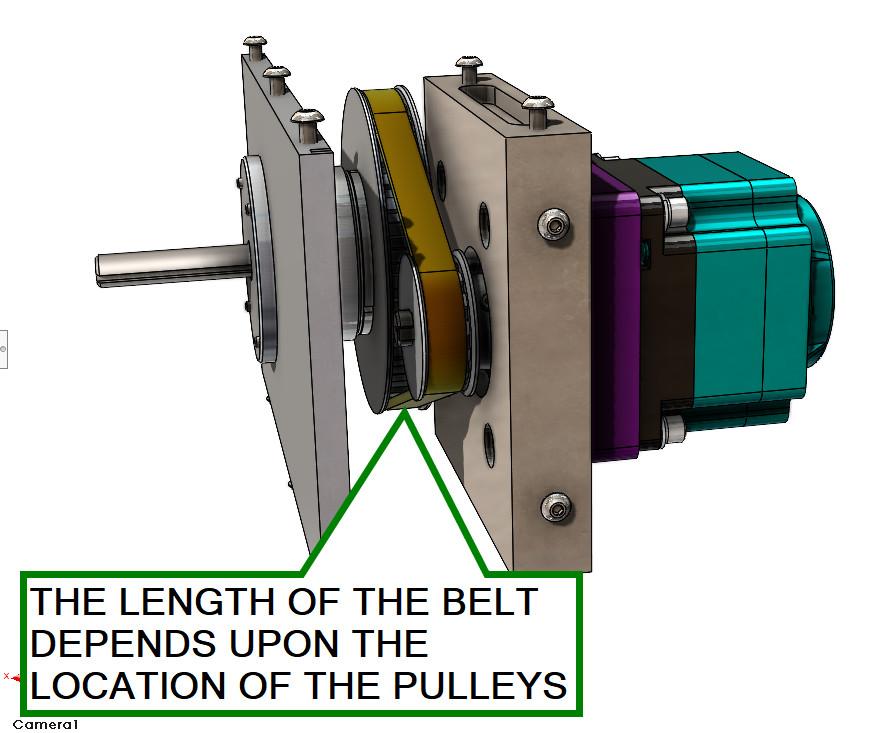
FIGURE 3. Not only the location, but the shape or length of a component can be linked to the location of other components in an assembly. Here, the timing belt is linked to the location of its pulleys.
However, once the item is in revision-controlled manufacturing, sustaining engineering does not benefit from cascading changes because of forgotten or arcane links. The parametrics become a curse. They are easy triggers for accidental edits.
If all related files and folders always travel together (perhaps as a zip file), the links are probably safe. However, there might be peril in the size of such a zip file. Additionally, if such a zip file were to fall into the wrong hands, the distribution of all intellectual property (linked files) would, of course, expand the disclosure of the design.
Tools to transition the model from fully parametric to locked and frozen with a few simple mouse clicks are available. The blessing there is that mouse clicks also unlock and thaw to allow shape changing and the altering of the chain of consequences.
If locking the links is too much overhead and requires too much discipline, an alternative (and the greatest waste of prior effort) is to release the model with all parametric links deleted. (That’s brute force CAD chopping!). Saving the project as a STEP file (or any 3D exchange format) is one way to strip out all links in a fell swoop.
A well-behaved CAD model is the result of planning and adherence to good policy. Sometimes the CAD Department Policy Manual comes before launching the CAD software.
Gerald would love for you to send him your comments and questions. You are not alone, and the problems you face often are shared by others. Share the grief, and perhaps we will all share in the joy of finding answers. Please send your questions and comments to ddavis@fmamfg.org.
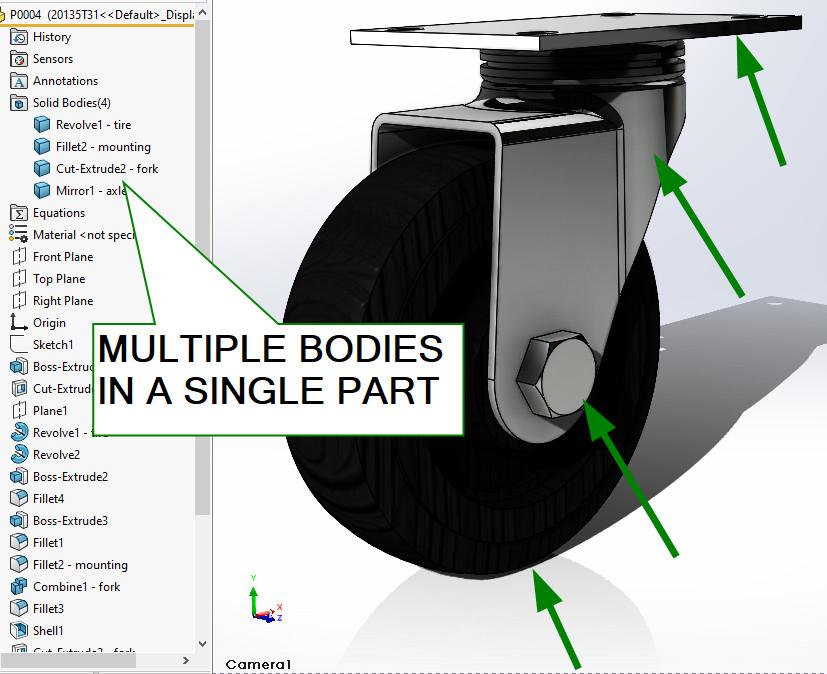
FIGURE 4. Some assemblies are not required. One part might have several bodies, and each body might be positioned. Each body might be saved to create a derived part.

The Fabricator is North America's leading magazine for the metal forming and fabricating industry. The magazine delivers the news, technical articles, and case histories that enable fabricators to do their jobs more efficiently. The Fabricator has served the industry since 1970.
start your free subscription


Easily access valuable industry resources now with full access to the digital edition of The Fabricator.

Easily access valuable industry resources now with full access to the digital edition of The Welder.

Easily access valuable industry resources now with full access to the digital edition of The Tube and Pipe Journal.

Easily access valuable industry resources now with full access to the digital edition of The Fabricator en Español.
In this episode of The Fabricator Podcast, Caleb Chamberlain, co-founder and CEO of OSH Cut, discusses his company’s...


