


Contributing Writer
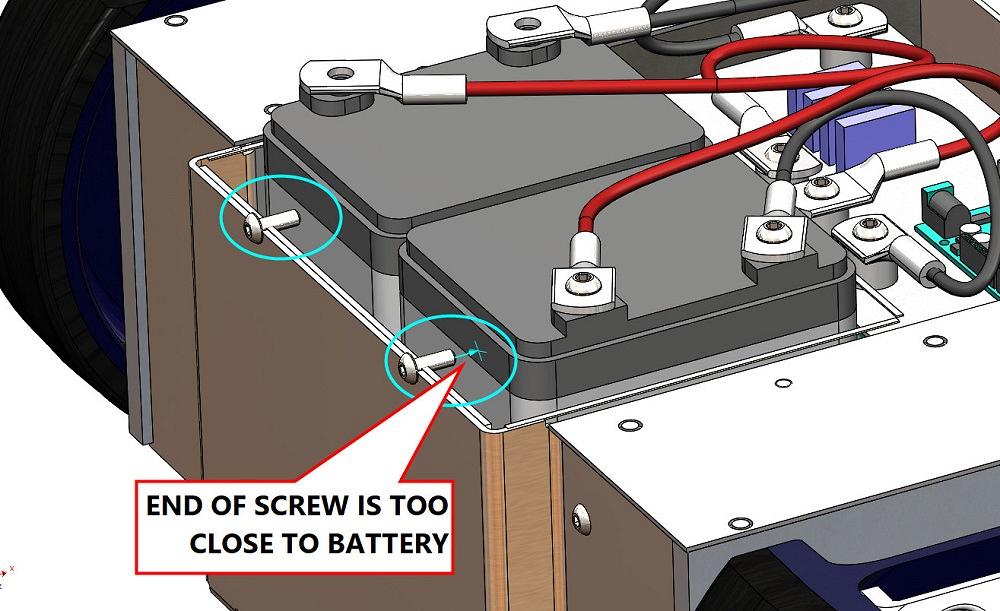
FIGURE 1A. A problem requires change. The side of the battery is endangered by the close proximity of screw tips.
What follows is a description of CAD activities involved in revising an existing drawing, one that is usually distributed as a PDF and maintained as a SLDDRW.
As a disclaimer, the brand of CAD and, most importantly, my drafting standards are specific to this demo. As examples of procedure and methods that are “as you like it,” I use logs (spreadsheets) here to issue part numbers and to serialize engineering change orders, as well as tables to document revision levels and required components.
Ready, aim, fire! In this scenario, getting ready means discovery of a problem, a solution, and a plan. Aiming is documentation of readiness. Hitting the bullseye is satisfying.
Figure 1A shows a problem with hardware length. The task is to produce a revised PDF that shows the corrected BOM (bill of materials) table. This length problem is the result of trying to use the same component everywhere to take advantage of the economies of scale. In this example, the ideal screw is 4 mm too long.
In Figure 1B, the engineering change (EC) log is being updated to show that the screw length should change from 14 mm to 10 mm. Because an existing part number for that screw length does not exist in the log, a new part number for the 10 mm is to be created.
Here is a side note: Our imagined policy for drawings is to show the EC number in the revision table and to otherwise rely on the log entry to be more fully descriptive if needed.
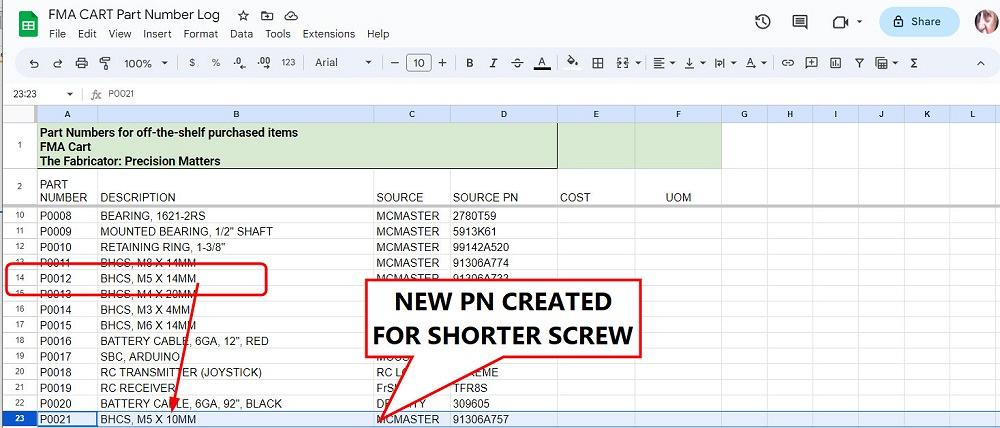
In Figure 1C, the part number (PN) log is updated.
One other note: Our imagined policy is to assign our part numbers to commodity items, such as hardware, or basically anything purchased by their specification rather than by our specification (drawing).
As a timesaver when creating the entry for the new item, old info was copied from a similar existing item and pasted as a starting point for the new entry. In this example, the row for P0012 was copied to a new row for P0021, and then simple edits completed P0021’s description and supplier information.
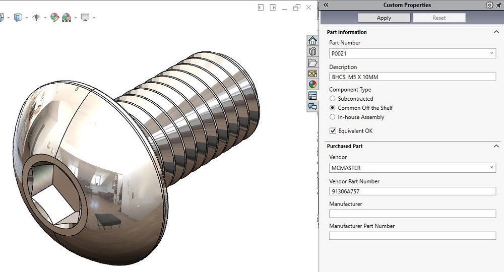
That’s progress in part number logging. Next, a 3D model that matches the part number is needed for visualization as well as for automatic population of BOM tables. To create the 3D model for the new PN, the similar-to-it model could be used and revised as needed. An alternative technique (importing it) is being demonstrated in Figure 2A. The supplier for this item provides downloads for 3D models.
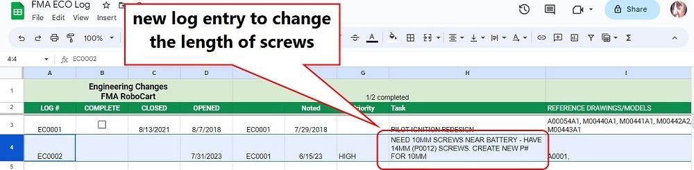
FIGURE 1B. A log is used to serialize and document changes made to drawings. The serial number for this EC is to appear in the revision table on the drawings.
Figure 2A shows the progress of importing a downloaded STEP file into a SLDPRT file. The product manufacturing information (PMI) is subsequently updated and reviewed using our custom property flyout form.
As a timesaver, the PMI could be copied from the existing model, pasted into the new model, and updated to show the correct description and supplier information.
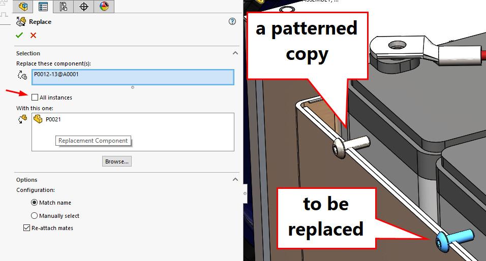
With the new 3D model’s perfect PMI in hand, the next task is to revise the 3D assembly. Figure 2B was created during the process of replacing the long screw (P0012) with the new screw (P0021).
The model replacement is done with caution. Per this EC, there are two—and only two–that need to be shorter. If the long screws are used elsewhere, they are not to be changed by this EC. Thus, the all instances check mark is not checked.
Conveniently, the screws in question are patterned. Only the seed component needs to be replaced with the shorter item. The other copies in the pattern are automatically updated from the seed. Were the to-be-replaced components not patterned, each instance would require a click for selection.
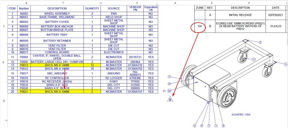
Figure 2C is a review of the PDF created from the updated SLDDRW, which was updated by the revised SLDAM. The PDF now shows the pattern of shorter screw models. With acknowledgment to the experts reading this, the pedantic recitation of the hierarchy of CAD file types is offered to those who are mostly familiar with using CAD to make flat layouts and are interested in what’s behind the curtain of sustaining engineering.
Continuing the review of Figure 2C, the BOM table now automatically updates to show the correct quantities for the longer screws (12 was 14) as well as for the shorter screws (item 20 is new). In our CAD shop, we prefer BOM tables to be sorted by number, not assembly order.
During the editing of the SLDDRW, an entry is added in the revision table, which can be seen in the top-right corner of Figure 2C. The description for revision B cites the EC log. This entry is brief, mostly a flag that something is different. The EC log’s description might be more verbose to explain the difference in detail to those who need to know.
The revision table’s Zone column updates to show where to look for the change on the drawing. For revision B, the change is near the intersection of row D and column 4. One or more revision symbols are placed during the editing of the SLDDRW to draw attention to the change. The Zone column in the revision table lists the locations of the revision symbols, if any.
In summary, a hierarchy of files and their functions is the law of the land in CAD work. One or more might be affected by a required change. Policy and procedure provide clarity on how to manage the variables. The log files are useful for coordination, review, and training of new team members.

The Fabricator is North America's leading magazine for the metal forming and fabricating industry. The magazine delivers the news, technical articles, and case histories that enable fabricators to do their jobs more efficiently. The Fabricator has served the industry since 1970.
start your free subscription


Easily access valuable industry resources now with full access to the digital edition of The Fabricator.

Easily access valuable industry resources now with full access to the digital edition of The Welder.

Easily access valuable industry resources now with full access to the digital edition of The Tube and Pipe Journal.

Easily access valuable industry resources now with full access to the digital edition of The Fabricator en Español.
In this episode of The Fabricator Podcast, Caleb Chamberlain, co-founder and CEO of OSH Cut, discusses his company’s...


