


Contributing Writer
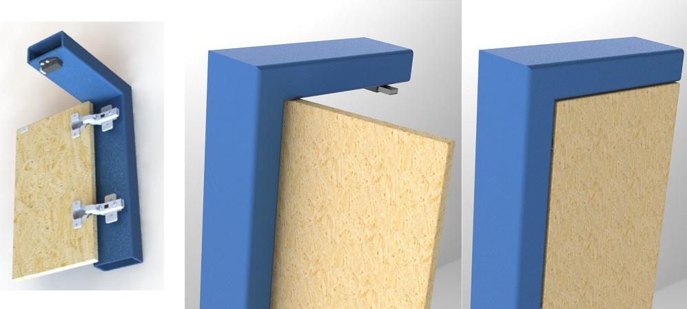
FIGURE 1. This hinged door is offered as a CAD modeling project. The design intent is to create an accurate bill of materials, as well as demonstrate proper motion and behavior.
Editor’s Note: Download files associated with this column here.
The CAD task at hand in this episode is to model a hinged door featuring a magnetic touch latch. A preview is shown in Figure 1.
We have two objectives for this model:
In the process of creating Figure 1, we’ll demonstrate a workflow of modeling an assembly (out of a myriad possible CAD techniques), so that the creation of a BOM table is just a few mouse clicks. The assembly technique also accommodates kinematic motion via the use of mates. Those mates, in turn, allow the mouse-drag demonstration of door motion in a live presentation.
The plan behind the workflow is to use a 10- by 8-in. opening as a starting point and to be prepared to change the size of anything. Please refer to Figure 2 while tracking the workflow:
At this point, with Figure 2, we have a virtual prototype in the making, but some problems need to be addressed. Most of the data in the BOM table is incomplete, and there is no motion.
We’ll focus on adding detail to this table after the door is swinging. (Don’t jump ahead and look at the other figures!) The lift-off hinge in Figure 2 turns out to be inappropriate for this project.
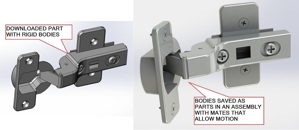
Figure 3 shows two versions of a model for the same half-mortice concealed hinge. A downloaded part is on the left. It arrives with several bodies, but they are all fixed in position. The hinge does not move.
A kinematic version is shown on the right in Figure 3. The CAD tool to save bodies from a multibody part has been used to create an assembly of several components; all of the components in that assembly start out in a fixed position, just like the bodies in the multibody parent part. We will be editing to the assembly to allow some of them to move.
For extra credit, materials and appearances were added to the components to give the assembly realistic mass and beauty. The cut sheet for the hinge says that it comes with mounting screws, so those were added to the assembly.
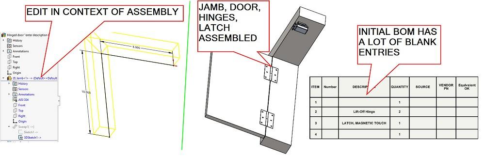
FIGURE 2. The path that defines the size of the door jamb is shown to the left. It is being edited in the context of the assembly. The jamb is modeled with a sweep. The initial BOM table is shown on the right. It’s very sparse and not useful—yet.
The parts that are to move were changed from fixed in position to floating. Mates were added to those components to allow the pivots in the mechanism to operate realistically. Planes were mated to keep the hinge aligned, and pins were mated concentrically with their sockets. A limit mate was added to keep the hinge swinging within the 100-degree advertised range.
It should be noted in Figure 3 that the morticed section of the hinge has been mouse-dragged into an intermediate position for demonstration of kinematics. It is more fun to move live in CAD.
When the hinge is inserted into an assembly, it can be set to be either rigid (default) or flexible (behaves within the constraints of its mate schema). When the hinge component is set to flexible, the door can be swung with the mouse.
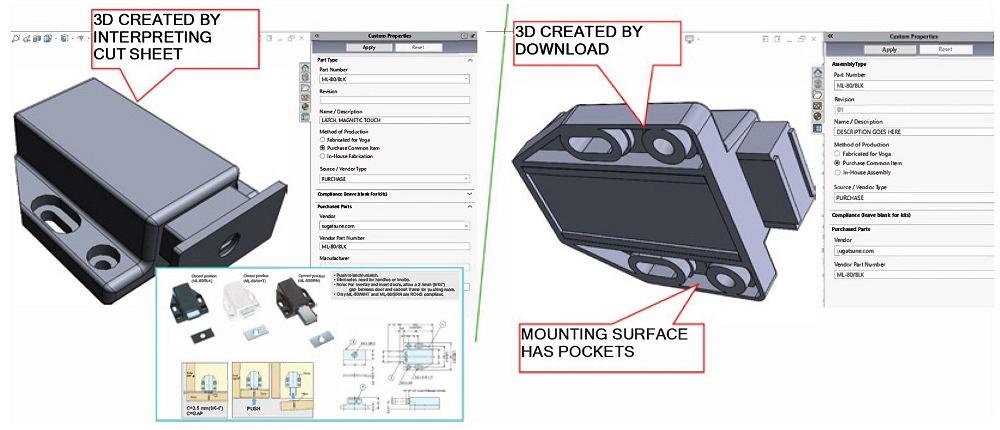
A similar problem (with rigid downloaded mechanisms) is shown in Figure 4. In this case, a magnetic touch latch is stuck. We offer thanks to Sugatsune.com for its publication of the 2D cut sheet and for providing an accurate 3D download to play with. It doesn’t reveal how the latch works, but it does show how the latch exists.
On the left in Figure 4, the 3D model was created by hand. It is probably as accurate as my interpretation of the PDF’s or cut sheet’s interpretation of the mechanism.
On the right in Figure 4, we see the downloaded 3D model from Sugatsune. The model reveals details that are not evident on the cut sheet.
As with the hinge, our downloaded latch gets special treatment to make it position accurately. There are three critical positions for the latch’s plunger. The latch must be depressed to toggle it from latched to an extended position. When extended, the magnetic field attracts only itself; when latched, it attracts like a normal magnet. Thus, the plunger’s positions we care about are extended, latched, and at the release stroke point.
The distance that the plunger protrudes is controlled with a distance mate and a design table to control that mate. The table has three entries: extended, latched, and release stroke. The mouse can’t be used to drag the plunger.
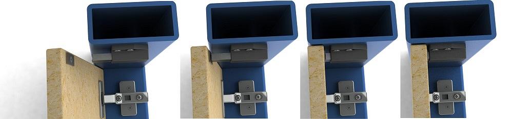
Figure 5 shows the door in four positions: swinging free, in contact with the extended latch, latched, and at the release position to toggle from latched or extended.
The CAD tricks used in Figure 5 include a vertex in the plunger mated in contact with the surface of the pole plate on the door and the selection of one of three latch configurations. For the leftmost pose, the contact-mate was suppressed to let the mouse drag the door. When this mate is not suppressed, the latch controls the position of the pole plate, which in turn controls the position of the door panel. The door panel is mated to the mortice section of the hinge, which is flexible to allow the pole plate to move with the latch’s plunger.
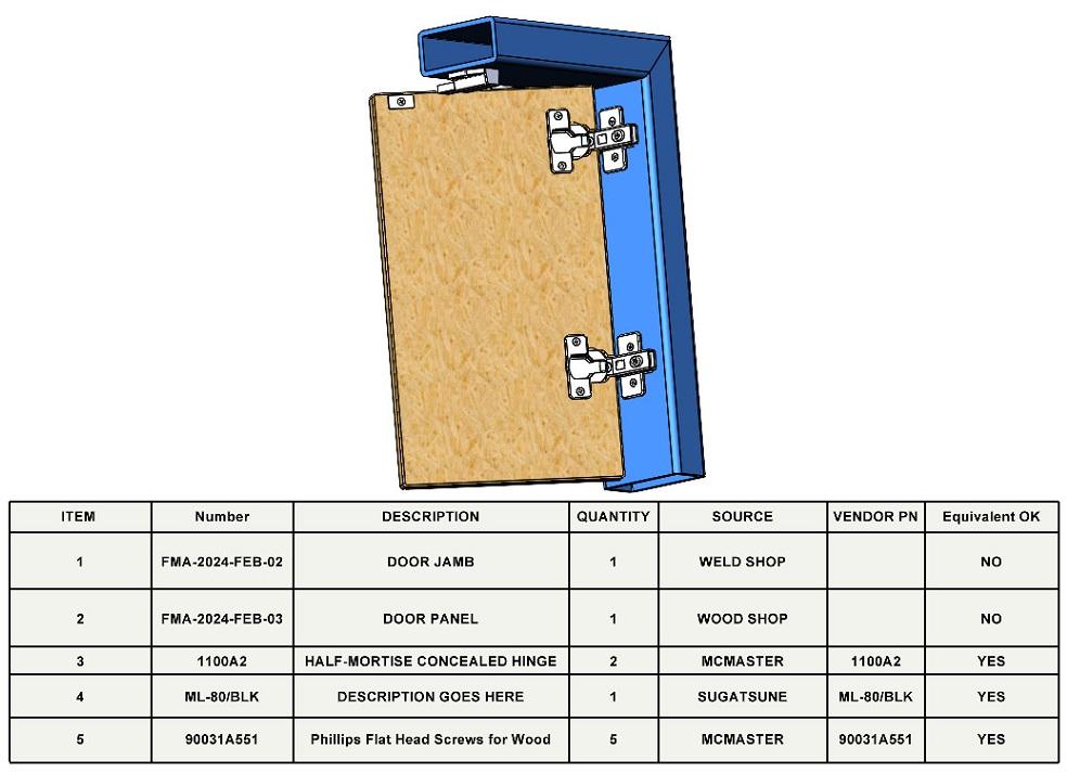
Figure 6 shows the results of a bit of data entry to get the BOM table up to speed. This was done with a combination of using the custom properties form and editing cells in the BOM table.

The Fabricator is North America's leading magazine for the metal forming and fabricating industry. The magazine delivers the news, technical articles, and case histories that enable fabricators to do their jobs more efficiently. The Fabricator has served the industry since 1970.
start your free subscription


Easily access valuable industry resources now with full access to the digital edition of The Fabricator.

Easily access valuable industry resources now with full access to the digital edition of The Welder.

Easily access valuable industry resources now with full access to the digital edition of The Tube and Pipe Journal.

Easily access valuable industry resources now with full access to the digital edition of The Fabricator en Español.
In this episode of The Fabricator Podcast, Caleb Chamberlain, co-founder and CEO of OSH Cut, discusses his company’s...


