


Contributing Writer
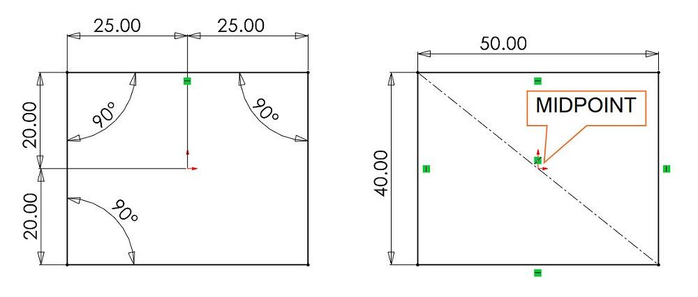
FIGURE 1. The rectangle on the left is explicitly dimensioned relative to the origin. The rectangle on the right relies on the rules of geometry to reduce the number of explicit dimensions, making it easier to edit the size and maintain symmetry about the origin.
I recently was asked what I do. As the guy running the CAD system, my job is to document the daydreams. I am a doodling stenographer. Instead of using shorthand, I sketch.
My most successful CAD projects have targeted fabrication (as opposed to something only for virtual reality). That observation is offered as a qualifier to the CAD wisdom offered here. I don’t sell software. I just use it. I have bias because of long exposure to a particular brand of mainstream 3D CAD.
3D design projects have three stages:Those stages of workflow seem to be governed by a rule of ratio: Half of the time is exploration, one-quarter is design optimization, and the other half is adding detail. (Yes, we know that it doesn’t add up. It’s Yogi Berra math.) Simply put, a significant amount of time is spent adding information that is expected by the various trades in the supply chain. This product manufacturing information includes tolerances, surface finish, and part numbers, all mostly documented in text form.
During the stage of exploration, the workflow requires imagining what to sketch and then sketching it so it can be changed. Most of the labor is mouse work, just clicking on menus along with some typing. Proficiency and versatility with the CAD software comes from practice and happy moments simply reading randomly through the help system.
Usually, a CAD jockey has more than one way to solve a modeling problem. Knowing those several ways is important to being able to select the better path. Selecting the better technique comes with experiencing the consequences of bad technique.
As a CAD technique, 3D modeling with solid extrudes is a skill set that covers a wide range of manufactured goods. Skill in 2D sketching helps with speed. Curved and flowing shapes are often modeled as surfaces and made into solid models as needed. Skill in 3D sketching helps with surface modeling. Note the repeated theme of sketching as a skill.
The workflow for drawings also involves sketching, albeit within the rules of a drafting standard. The various sketches in these workflows might individually take a few moments to create, but there are many of those sketchy moments. That’s an opportunity to save many small bits of time.
A dilemma in sketching is the trade-off between ordinary dimensions—human readability—and sketch relations, which means less typing. The latter also is more reliable than human memory of intent. For those experienced in 2D CAD sketching, dimensioning (specifying angles and lengths of lines) is part of doing business. Dimensioning is the principal task when drafting the drawings.
Having the CAD system insert the dimensions from the model into the drawing is a time-saver. Thus, sketching while modeling can impact the production of detailed drawings. But don’t slow down the exploration just to make the drafting easier.
As opposed to dimensions, sketch relationships (symmetry, concentricity, piercing, and similar) are techniques less used when drafting drawings and more often used in sketches for modeling.
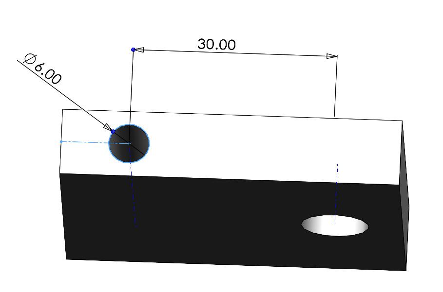
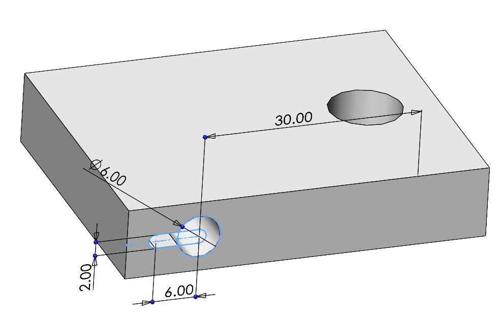
FIGURE 2. A temporary axis can be used as reference geometry in a sketch. When the temporary axis is invisible, the sketch becomes less intuitive. Training might be needed for those who edit the model to enable the display of such axis.
As an alternative to simply specifying lengths and angles, a CAD workflow for modeling might include the creation of construction geometry, the use of dynamic mirroring, use of a temporary axis, and the application of the Hole Wizard for the benefit of creating a pattern of components. Emphasize relationships more than exact dimensions when developing a virtual prototype.
An objection to using exotic sketching methods is that the setup process takes as much time as simply typing dimensions and angles. Furthermore, dimensions in the sketch are more intuitive to edit than what may be invisible sketch relations. If it takes longer to understand before editing, little efficiency is achieved.
To some extent, the efficiency of computation matters. The 3D model is basically a complex math equation. The more steps it takes to solve the equation, the more time the human waits on the computer. Every line or dimension added takes time to compute.
Consider the task of sketching a rectangle that is centered on the origin. Figure 1 presents two approaches side by side for comparison. In both sketches, the CAD system has displayed little green icons that represent sketch relationships. (They are much easier to interpret on a computer monitor.) The important point here is that more sketch relationships can be found on the right sketch than on the left.
On the left in Figure 1, the dimensions specify that the left-right and top-bottom distances are identical. Horizontal and vertical relationships are replaced with angle (90-degree) dimensions. This is very easy to interpret.
On the right in Figure 1, horizontal and vertical relationships are used instead of angled dimensions. The 90-degree angles are implied rather than stated. A construction line’s midpoint is constrained to the origin, with its endpoints at the diagonal intersection of the rectangle. This geometrically constrains the rectangle to be symmetric about the origin. One dimension controls the width, not two.
The difference between a temporary axis and an ordinary axis is that the software generates the temporary axis, and the operator must create the ordinary axis. Other than that, both types of axes offer the same functionality for sketch relationships.
The CAD system can hide or show the axis—a temporary axis is found at the imaginary centerline of a cylinder, for example. This can be a speedy resource.
When an axis is displayed, it might be used in sketch relationships. Figure 2 shows a sketch that dimensions the location of a hole relative to a temporary axis. The relationship persists whether the axis is displayed or not. When the axis is hidden, will the next person be able to interpret the intent? With training on hide/show, yes. Don’t hesitate to use speedy resources when sketching.
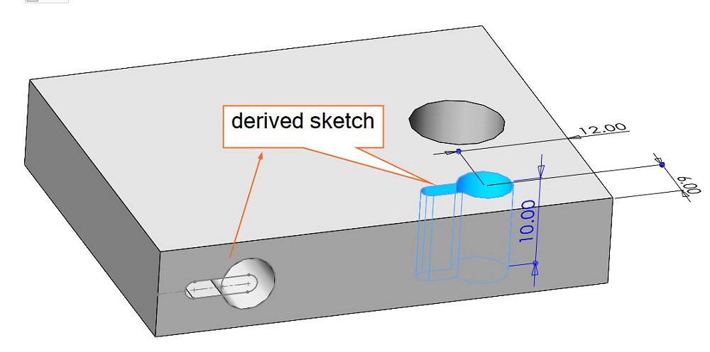
It is possible to copy-paste the geometry from one sketch to another. However, the derived sketch might be a speedier technique if both sketches are to be identical.
Figure 3A shows a sketch for a cut-extrude—in this example, a slotted hole. If the task is to duplicate that cut in a different location, the technique of using a derived sketch might do the trick. Figure 3B shows a derived sketch being used to create the same cut by simply CTRL-selecting both the sketch and the target surface and then adding dimensions to locate the feature. (Selecting insert in the previous exercise is a much better decision than selecting the derived sketch from the menu.)

The Fabricator is North America's leading magazine for the metal forming and fabricating industry. The magazine delivers the news, technical articles, and case histories that enable fabricators to do their jobs more efficiently. The Fabricator has served the industry since 1970.
start your free subscription


Easily access valuable industry resources now with full access to the digital edition of The Fabricator.

Easily access valuable industry resources now with full access to the digital edition of The Welder.

Easily access valuable industry resources now with full access to the digital edition of The Tube and Pipe Journal.

Easily access valuable industry resources now with full access to the digital edition of The Fabricator en Español.
In this episode of The Fabricator Podcast, Caleb Chamberlain, co-founder and CEO of OSH Cut, discusses his company’s...


