


Orbital welding unit helps build mission-critical piping systems for rocket launch tower
Robust welding system makes reliable welds for multitude of gas, liquid, cryogenic supply systems
Building a launch tower from scratch involves no shortage of potential interferences among electrical, piping, and mechanical systems. A retrofit or refurbishment project complicates these interferences to an extraordinary degree. Orbital welding is well-suited to such projects because the hardware fits into confined areas that welders cannot access easily, or at all, greatly simplifying circumferential welds.
Launching a rocket should be easy, shouldn’t it? You start with a de Laval nozzle, which looks a bit like an hourglass; add a fuel tank and a device for mixing the fuel with air; and finally, add an ignition source. The air-fuel mixture goes in the top, thrust squirts out the bottom, and presto! The rocket scoots toward the stratosphere.
It’s nothing new. An early version of this, using gunpowder to launch an arrow, dates back about 1,000 years; Gustav de Laval developed his famous nozzle for steam power in 1888; and in 1914 Robert Goddard applied for two key patents, one for liquid-propelled rockets and one for multistage rockets. Goddard also envisioned three-axis control, gyroscopes, and steerable thrust in 1919 to keep a rocket’s path straight and true. The modern concepts used in rocketry today are nearly a century old. How hard can it be?
Well, it’s pretty hard. Despite a century of progress, lobbing a rocket into outer space is never an easy endeavor. Although the laws of physics don’t change, the technologies used for rocket propulsion and guidance grow more complex over time, and it’s safe to say that successful launches actually grow more difficult as time goes on.
Digging deeper reveals that building a rocket only gets you halfway to a launch anyway. To go all the way, you need to build a launch tower, too. Fastened to the rocket, the launch tower supplies electrical power, helium, nitrogen, and fuel to the rocket and provides stability and guidance as the rocket lifts off. Although the rocket gets all the attention and the glory, a modern launcher is almost on par with the rocket in the complexity of its onboard systems and the functions it provides.
Every Rocket Needs a Launch Tower
Some items don’t work well, or do anything, without a complement. Locks need keys, wheels need axles, pistons need crankshafts, and rockets need launch towers. Also known by more descriptive names, such as service structure or supply tower, a launch tower is akin to a common 10-story building, such as a hotel. Although most hotel guests stay in a room and perhaps swim in the hotel pool, few probably give a lot of thought to the heating, ventilation, air-conditioning, electrical, plumbing, and fire-suppression systems that keeps the rooms comfortable and safe. A launch tower is like that—it looks simple on the outside, but the exterior hides several complex systems and subsystems that make launches possible.
The launch tower’s basic purpose is one that served even the earliest and simplest rockets: it provides stability for the rocket after the initial ignition, while thrust is building but before liftoff. In layman’s terms, it prevents the rocket from tipping over. It provides support and directional guidance until the rocket begins to accelerate and its onboard guidance systems take over.
Second, a support structure provides electrical services in the form of electric power, communication capability, and transfer of telemetry data. Accordingly, the launcher is outfitted with sophisticated power and communications systems supported by mile upon mile of power cable and fiber-optic cable, countless control panels, vast amounts of switchgear, and numerous fuse panels.
Third, the launch tower supplies fuel, gaseous nitrogen, and gaseous helium to the rocket. In the moments before launch, the boosters burn off a substantial amount of fuel; in many cases, a successful launch requires full tanks at the point of liftoff, so while fuel is burning and the process is building thrust, the launch tower supplies additional fuel to replenish the tanks. No point in taking off on a long trip without filling up first.
A fourth major component on nearly every launch tower is a sound suppression system designed to absorb the tremendous noise generated by the combustion process.
Unlike a hotel, which is a stand-alone building, the launch tower is fastened to the rocket. The two are assembled as a unit, and the launch tower restrains the rocket as the thrust builds up. When the rocket has developed a sufficient amount lift, the two are separated—explosive bolts are detonated, uncoupling the tower from the rocket—and the rocket takes off, well, like a rocket.
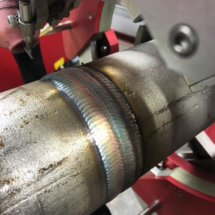
Figure 1
An orbital welding machine’s oscillation mechanism guides the tungsten electrode back and forth as the unit weld two pipe faces together. Smooth oscillation contributes to weld quality, and on J.P. Donovan’s mobile launcher overhaul project, just two welds out of 400 needed rework, a success rate of 99.995 percent.
Another big difference between a launch tower and a hotel, of course, is system reliability. While the systems in a hotel have to be robust and durable, they aren’t necessarily mission-critical. If a pipe in one of the rooms springs a leak, shutting off the water supply to that room and moving the guests to an empty room is simple enough. If an air-conditioning unit goes out, the guests have to deal with some discomfort until they can move to a different room or a different hotel. Not a big deal.
On a launch tower—more appropriately, a mobile launcher—the systems indeed are mission-critical. The electrical systems must be designed to be robust and installed to specification. The piping systems likewise must be designed for the proper capacity, the components must be manufactured to exacting standards, and the welds must be performed flawlessly. Nobody wants to risk a using a substandard part, cutting corners in an installation, or performing a subpar weld.
Making Orbital Welds for Sending Orion into Orbit
The latest big directive for the National Aeronautics and Space Administration (NASA) is to visit Mars. Just as the moon shots of the Apollo missions were built on the many lessons learned from the Mercury and Gemini programs, NASA’s Journey to Mars isn’t a single lift, but dozens or perhaps scores of launches.
Beyond that, comparisons between a trip to the moon and a trip to Mars are few. At its furthest, the moon is 252,700 miles; the Apollo journeys took about three days. When the distance to Mars is at its shortest, it’s 35 million miles away. The many successful fly-by, orbiter, and lander missions sent to Mars have needed about 275 days to reach the vicinity of the Red Planet. This isn’t to suggest that the four Apollo landings were easy, but the logistical planning for reaching Mars is more complex by an order of magnitude.
Modifying an existing launch tower might seem like a puny task in comparison, but it’s not; it’s a daunting task, but on a smaller scale. J.P. Donovan, a primary contractor well-versed in NASA projects, won a bid to modify an existing launcher for one of the early Orion launches. As the prime contractor, the company is responsible for the cost, schedule, safety, management, subcontractor management, and technical performance of this multidisciplinary project. A list of the key personnel for the project highlights the scope of this overhaul: John Donovan, owner; Julian Acosta, project supervisor; Mike Taylor, project manager; Tyler Reith, mechanical engineer; Tim Dougan, aerospace systems coordinator; and Frank York, welding supervisor and owner of Advanced Automated Welding.
York’s experience in welding goes back to 1982 and includes a year-long stint supervising a pipe replacement project in a nuclear power plant, eight years in welding equipment product development, more than 10 years in writing welding procedures, and 25 years in welding equipment sales. One of his stints in writing and implementing welding procedures included work for NASA, so York was right at home in this always-stringent, occasionally hectic environment.
- Welding, fabrication, and assembly of structural steel components and entire structural systems.
- Fabrication, installation, and testing of ground support equipment systems.
- Installation and testing of electrical, mechanical, and piping systems for power, communication, hydraulics, gaseous helium, gaseous nitrogen, and cryogenics.
- Electrical consoles for control, monitoring, and testing functions.
- Interfaces to existing facility systems and structures.
A project estimated to take 36 months, from September 2015 to March 2018, it includes an array of piping systems that would make any pipefitter or pipe welder smile:
- 2-inch Schedule 40 for hydraulic line at 98 pounds per square in. (PSI)
- 2-in. Sch. 160 for gaseous helium at 3,600 PSI
- 2-in. Sch. XXS for gaseous helium at 5,600 PSI
- 2.5-in. Sch. 40 for hydraulics at 97 PSI
- 3-in. Sch. 40 for hydraulic return at 1,200 PSI
- 3-in. Sch. 160 for hydraulic supply at 3,500 PSI
- 3-in. Sch. XXS for the gaseous helium and gaseous nitrogen at 5,600 PSI
- 3.5-in. Sch. 40 for hydraulic return at 100 PSI
- 4-in. Sch. 10 for gaseous nitrogen vent at 100 PSI
- 4-in. Sch. 40 for gaseous nitrogen at 150 PSI
- 6-in. Sch. 10 for cryogenic lines
- 8-in. Sch. 10 for cryogenic line and gaseous nitrogen vent line
- 10-in. Sch. 10 for cryogenic line
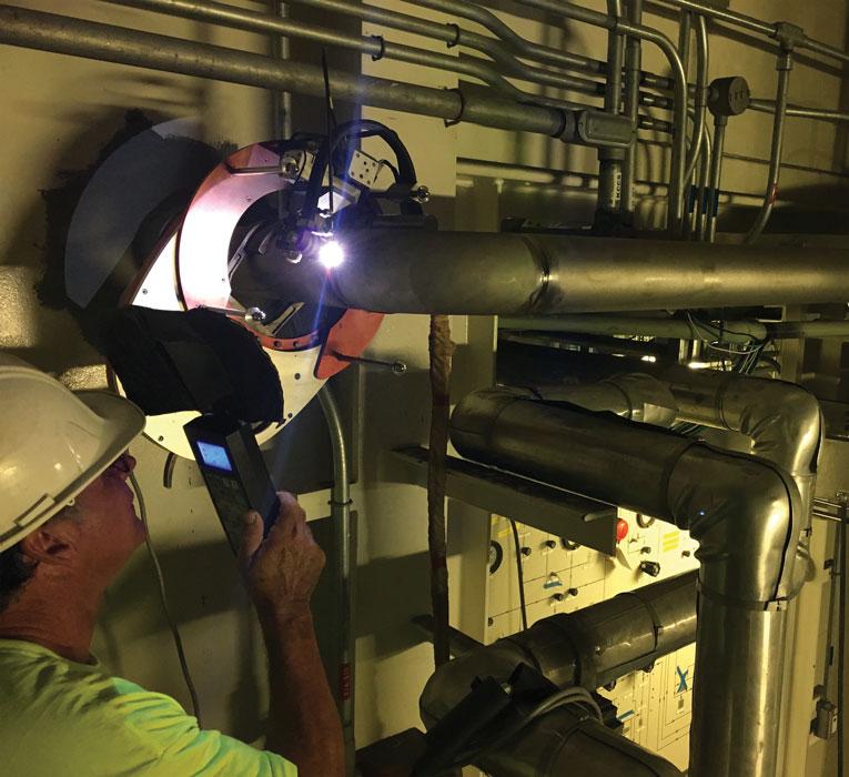
- Anyone who has done some retrofitting or modification work knows that such projects usually include an endless series of compromises, and this one is no different. The layout of the launcher isn’t ideal. Bulkheads and doors aren’t in ideal locations, and the pipefitters, electricians, and iron workers have to work around each other’s pipe, conduit, and structural steel, not to mention other mechanical systems and components that were installed previously (see Lead Image).
It gets even hairier. Some of the pipe lengths vary when they are put into use. A length of pipe at room temperature can shrink significantly when liquid hydrogen or liquid helium runs through it. These elements turn to liquid at -423 and -452 degrees F respectively, so the temperature swing is about 500 degrees in total. This caused some fit-up issues on these lines, which have mandatory inspection points, York said, so to compensate, the welding team had to install expansion joints on the cryogenic lines.
York also had to pay close attention to the variety of wall thicknesses. For this project, welding in the low end of the range up to the middle, Sch. 40, the wall thicknesses don’t pose big challenges. In diameters from 2 to 4 in. on Sch. 40, the wall thickness is 0.154 to 0.237 in. That’s manageable without any particular difficulty. However, the heavier schedules raise a few eyebrows. More material means more heat, which means more current. The 3-in. XXS would be the biggest challenge at 0.5984-in. wall thickness. J.P. Donovan would need a welding unit capable of delivering a lot of current, and because this was a big project on a tight timeline, it needed a respectable duty cycle. The contractor couldn’t afford to have welders waiting long periods of time for the welding units to cool down.
There was no question that the job required orbital welding. Developed 50 years ago and refined ever since, the orbital welding process is preferred for these types of projects because they can get into tight, cramped areas that welders simply can’t get to, and they are capable of producing X-ray-quality welds consistently.
At York’s suggestion, Donovan selected the Otto Arc model OW-ARC-450 as the orbital welding power supply. As the name implies, it’s a 450-amp machine. It has a 60 percent duty cycle at 450 amps and 100 percent duty cycle at 310 amps.
For the weld heads, Donovan chose a model TPWH-0A-3 for pipe sizes from 1½ to 3.00 in. and the model TPWH-0A-7 for pipe sizes from 4.00 to 6.00 in. These would cover all the high-pressure piping. It also chose a TPWH-0A-12 for pipe sizes from 6.00 to 12.00 in., including the Sch. 10 jacketed cryogenic pipe.
A critical reason for choosing these weld heads concerns weld quality, York said. The two main elements York cited are arc voltage control (AVC) and the oscillation mechanism. As the tungsten electrode erodes away, its shape changes slightly and the distance between the electrode and the pipe can change accordingly. This change in distance can affect the weld quality, but the AVC compensates for this. It senses the change in distance and adjusts the voltage to maintain enough current to keep the weld heat consistent as the weld progresses. The oscillation mechanism guides the tungsten electrode back and forth as it weaves its way along the groove, from one pipe end to the other, to make the weld (see Figure 1).
Two contributors to weld quality are how the AVC adjusts the welding parameters and how the oscillation mechanism moves the electrode along its path. For both criteria, smoother is better. Abrupt changes in the AVC and sudden changes in electrode direction don’t contribute to a good weld.
“These are some of the smoothest weld heads I have ever seen,” York said.
This isn’t to say that the team didn’t use manual welding at all. Some of the jacketed cryogenic pipes were too out-of-round for a standard J prep, which is required for orbital welding. These pipes, left over from a previous project—NASA reuses materials when it can—were cut too close to an existing weld, leaving them deformed, so they were welded manually.
The project is close to completion, and the X-ray records speak for themselves and York’s recommendation. Of the 400 orbital welds completed for this project, just two needed rework. The two that didn’t pass inspection were made at the beginning of the job when weld procedures were still being refined, York added.
Celebrating on Oct. 19
Goddard was far more than a ground-breaking scientist. He was a visionary without peer. When he was 17 years old, he climbed a tree to trim some dead limbs and was captivated by the view. His mind raced. He wondered about the potential to build some sort of a vehicle that could carry man skyward. However, his vision didn’t end there. He wasn’t merely thinking about reaching the clouds, or the moon, but other planets. The year was 1899. Lighter-than-air craft, specifically hot-air balloons, had been in use more than 100 years, but this was four years before the Wright brothers took off at Kitty Hawk and flew into the history books with the first manned heavier-than-air flight.
Goddard later wrote that he “imagined how wonderful it would be to make some device which had even the possibility of ascending to Mars…” and he celebrated this day, October 19, every year for the rest of his life.
Mars? Yes, Mars. He picked Mars, and NASA’s Journey to Mars timeline projects a manned orbiter to visit the fourth rock from the sun 135 years after Goddard’s flash of insight.
Otto Arc Systems, www.ottoarc.com
About the Author

About the Publication

subscribe now

The Tube and Pipe Journal became the first magazine dedicated to serving the metal tube and pipe industry in 1990. Today, it remains the only North American publication devoted to this industry, and it has become the most trusted source of information for tube and pipe professionals.
start your free subscription- Stay connected from anywhere

Easily access valuable industry resources now with full access to the digital edition of The Fabricator.

Easily access valuable industry resources now with full access to the digital edition of The Welder.

Easily access valuable industry resources now with full access to the digital edition of The Tube and Pipe Journal.

Easily access valuable industry resources now with full access to the digital edition of The Fabricator en Español.
- Podcasting

In this episode of The Fabricator Podcast, Caleb Chamberlain, co-founder and CEO of OSH Cut, discusses his company’s...
- Trending Articles
1
Zekelman Industries to invest $120 million in Arkansas expansion

2
3D laser tube cutting system available in 3, 4, or 5 kW

3
Corrosion-inhibiting coating can be peeled off after use

4
Brushless copper tubing cutter adjusts to ODs up to 2-1/8 in.

5
HGG Profiling Equipment names area sales manager
