


A worldwide view from Düsseldorf

This view of the New York City skyline illustrates the international scope of Tube®, the biennial tube and pipe expo held in Düsseldorf, Germany. Some of the machines used to fabricate the steel used in the Santiago Calatrava sculpture (foreground) were manufactured by G.B.C. in Italy and displayed at Tube.
While most architectural projects throughout the world are utilitarian in design—that is to say, rectangular—a handful stand out for taking on the orthodoxy and showing how flowing curves and gently sweeping contours can make a structure both functional in its use and breathtaking in its appearance. Architects such as Frank Gehry, Thom Mayne, Eric Owen Moss, and Santiago Calatrava are known for works such as the Walt Disney Concert Hall (Los Angeles), 41 Cooper Square (New York), Samitaur Tower (Culver City, Calif.), and the Museum of Tomorrow (Rio de Janeiro).
When the Port Authority of New York and New Jersey—owner of the site of the former World Trade Center—finished clearing the debris from the terror attacks of Sept. 11, 2001, it decided to turn the former building site into a subway terminal. It wouldn’t be just any subway terminal, but a beautiful symbol of hope and perhaps rebirth. Calatrava created a sculpture that resembles the wings of a bird, outstretched and preparing for flight (see Lead Image).
Of course, the structure is rich in metals, and one of the exhibitors at Tube® 2018 (April 16-20, Düsseldorf, Germany) can claim a small stake in the success of this construction project. The company, G.B.C. Industrial Tools S.p.A., which makes a substantial number of cutting, beveling, grinding, and facing tools for tube, pipe, and plate, provided a grinding system for back-gouging some of the heavy structural plate used in building the terminal. An alternative to arc gouging, grinding makes less noise and generates less debris.
“Arc gouging can be really dangerous,” said Guilio Baiguera, area manager for G.B.C., commenting on the risks associated with the noise and the red-hot metal the process ejects from the workpiece. For working in close quarters or an area in which a hot-work permit is difficult to get or not allowed at all, grinding is an alternative. For the building contractor working on this job, G.B.C. built a custom machine—a combination of its G300, a compact, maneuverable grinder, and the trolley used for its G800 machine. The result is a small version of the G800 that travels on a rail-mounted system for back-gouging lengthy workpieces. This custom system uses an abrasive disc 11.75 inches in diameter that rotates at 4,000 revolutions per minute and travels from 1.5 to 13 feet per minute. Safety features include built-in fume extractors and visual monitors so the operator can keep a close eye on the work from a distance.
This was just one of many examples of an exhibitor showing a new, unique, or custom machine, or displaying a machine that is the culmination of decades of updates, upgrades, and refinements.
Modern Machines for Modern Applications
Founded in 1982, G.B.C. has more than three decades of experience in manufacturing machines for pipe work—cutting, beveling, grinding, gouging, and facing. A typical innovation is its Fast machine, a split-body pipe cutter and beveler that works on diameters from 6 to 36 in. Unlike most similar machines that have four adjustment points, this one has a single-point adjustment that centers the machine. The operator turns a single screw that adjusts the four positioning feet simultaneously to clamp the machine to the pipe while centering it.
The company has come up with a variety of innovations that it uses on many of its tools:
- A series of orbital cutters, models Pipe 4, Pipe 6, and Pipe 8 (which cut pipe diameters up to 4.5, 6, and 8 in., respectively), likewise have the same self-centering capability. Setting any of these machines to a specific cut location is simple—for a cut located 1 in. from the pipe end, the user slips the machine onto the pipe end and uses the built-in height gauge to set the cut location 1 in. from the end. A cam-and-slide system ensures the machine is perpendicular to the pipe.
- As the name implies, its Multiedge can grind a variety of edges on plate. It can be set to any angle from 0 to 90 degrees for facing, beveling, or cladding removal, and cladding removal can be combined with a 45-degree bevel, 90-degree finish, or a J prep. The company furnishes nine tools.
- The Mini Auto Compact, designed for boiler and heat exchanger work, performs three tasks: it faces tubes, removes weld beads, and prepares the tubesheet. All the controls, including the pneumatic control valve—formerly separate from the unit—are built into the machine, making it convenient to operate. An adjustable automatic depth stop and an automatic feed rate help to ensure consistency from one tube or bore to the next.
And, while keeping hand tools as light as possible is always a goal, G.B.C. added an attachment eye so the operator can use a tether to support the tool’s weight, making it easier to handle, especially on big jobs.
- For gouging pipe, the company developed a unit that senses ovality and compensates accordingly.
“It adjusts to the pipe’s ovality to keep the groove depth consistent,” Baiguera said. Without this capability, the groove depth would vary. If the groove were to become too deep, it would be at risk of a blow-through during the subsequent welding process. Another innovation is a cutting unit, model TAF, that crawls around the circumference. Secured to the pipe by two chains, the unit has a central rail that guides the cutting unit.
“Because it follows the belt, it always ends where it started, making a continuous cut,” he said. “Without this capability, the cut might not be continuous. If the cutting doesn’t end where it starts, the groove has a step in it, which the user has to grind down the step by hand,” he said.
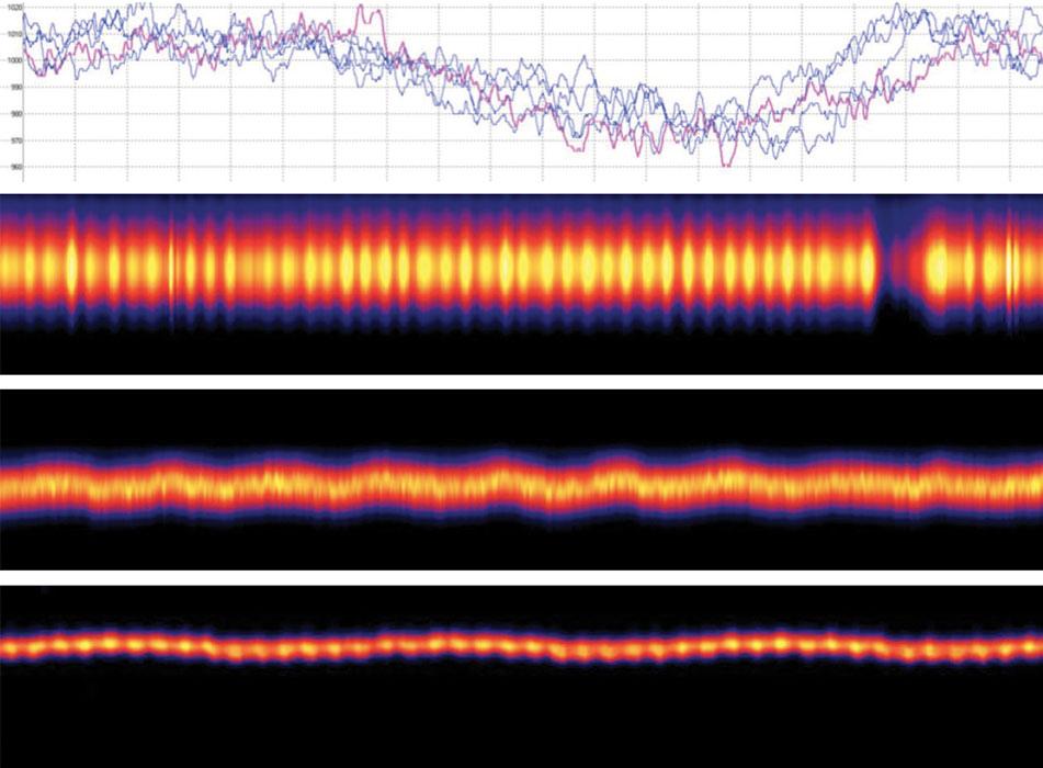
Figure 1
Row 1: When a single piece of equipment doesn’t keep pace with the mill, the mill speed variations cause a gradual cooling at the weld seam. Rows 2, 3, and 4: A broken drive component, worn bearing, and worn-out scarfing tool cause repeated patterns of temperature variation, lateral motion, or both.
Despite the differences in shape, tubulars and plate require many of the same processes for cutting and weld prep. G.B.C. often adapts its machines, using booms and trolleys for plate machines and circumferential systems for tubular equipment, but its versatility doesn’t end there.
“G.B.C. can modify any of its machines to match a customer’s specifications,” Baiguera said.
Another company that focuses on pipe installations and repairs, Serco, demonstrated a flange-facing unit, its XP-600. An alternative to removing a flange and sending it offsite for resurfacing, a flange-facing machine allows a worker to get the job done on-site. The key is that after the repair is finished, the flange face must have essentially the same characteristics that it had when it was produced in the controlled environment of a manufacturing facility, machined on a large, stable, stationary machine.
“Serco’s first flange-facing unit was developed for a nuclear application because the valves were welded onto the pipes,” said Solutions Engineer Benjamin Audigier. “Serco developed the machine and provided the service, so the company was its own customer.
“Flange facings must be flat and concentric, and on Serco machines, these settings are independent of each other,” he said. According to Serco, its machines are the only ones in the world that keep these two settings independent.
The unit is secured to the valve or flange by means of four columns that the user affixes to the bolt holes around the circumference. The operator then sets the flatness of the machine by using a comparator at each of the four columns and locks this setting into place. He
then moves the machine’s head to the center of the circumference and locks that position.
The company specifies that its machine achieve a flatness precision of 10 microns and surface finish of 1.6 Ra. Model XP 600 can be affixed to diameters from 7.9 to 23.6 in.; its XP 2200 can be clamped to diameters from 25.6 to 96.5 in., and it has other machines that cover intermediate sizes. The machines are available in electric, pneumatic, and hydraulic variants.
Its FSTG and tiltable head accessories expand the capabilities of all but the XP 600. The FSTG clamps onto the dowel pin bores to machine the sealing surfaces and the dowel pin bearing surfaces. The tiltable head is for boring, conical machining, and machining ring-type joint (RTJ) grooves.
Tri Tool also makes a variety of off-the-shelf and custom-engineered products. Lane Larson, group technical manager of international sales for Tri Tool, summed up the ethos that drives customization: “The customer wants something that’s not available, so we’ll make it available.” It might be for a different use or it might be for a different industry.
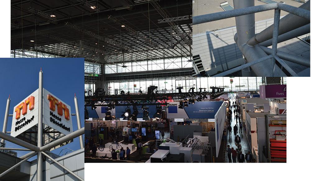
Figure 2
The interior and exterior of Messe Düsseldorf’s Hall 6 are showcases of structural tubing.
A case in point was a modification of its 572AC SEVERMASTER™, a bench-mounted machine designed for severing tube and pipe from 0.25 to 2 in. dia.
“A customer wanted a grooving machine for pipe in that diameter range, so we designed a similar machine that used a different blade, and we incorporated a depth stop,” Lane said.
Another example involved the company’s series of OD-mounted cutting tools. Its standard machines handle diameters from 1⁄8 to 72 in., but Larson recalled making a similar machine that went up to 100 in. dia. for a tank manufacturing application.
Tri Tool equipment is used in the oil and gas industry, as well as for cutting tube, pipe, flange, fittings, and microfittings for semiconductor manufacturing, aerospace, and chemical processing applications.
Bending, Forming, and Cutting
As always, bending, forming and cutting technologies were among the main attractions at the expo.
A manufacturer of machines for bending, forming, cutting, and even cleaning, transfluid Maschinenbau GmbH has benders that span diameters from 0.16 to 12.8 in. and, more importantly, software that can connect several machines to create a specified fabrication process, said CEO Stefanie Flaeper.
Like many other manufacturers, transfluid has product lines of standard machines suitable for many industries and specialized machines for niche applications, which facilitate the spread of ideas. A modification or feature developed for one industry, subsequently identified as a benefit in another industry, enables equipment vendors to provide a continuous stream of innovations.
“There’s really no limitation to modifying a machine,” Flaeper said.
While some still debate whether to specify electric or hydraulic, Flaeper thinks most of that is in the past. Initially the difference was a tradeoff between precision and speed. Nobody doubts the precision of an electric servomotor or the speed of a hydraulic drive system, but Flaeper is confident that the positioning accuracy of hydraulic systems can be worked out and the debate is essentially settled. The industry isn’t going to abandon hydraulic systems anytime soon, so with two contenders of comparable accuracy, the factors now are bending force and cycle times.
Although Herber isn’t the largest bender manufacturer in the world—its staff is just a few dozen people—this doesn’t mean that the company hasn’t earned some recognition for making high-end machines with some clever innovations. At Tube it displayed its model 150RL, an electric, 9-axis machine that handles tube up to 3 in. dia. As the name implies, it can make right- and left-hand bends, and stacked tooling allows it to process up to three diameters without changing the dies.
Figure 3
Tubular trusses that measure more than 10 ft. high are critical components in the pillar-free construction of the new Hall 1.
“It’s intended for high-volume applications, especially customers who run 24/7,” said CEO Andreas Nord. The programmability, the number of axes, and the stacked tooling also mean that it’s a highly flexible machine, he explained. Having three sets of tooling on the machine at any given time reduces the need for setups, saving on time and the need for a skilled worker to change out the tooling. This presents an interesting challenge, Nord said: building a high-tech and efficient machine that is easy to run. As the builder adds features and the machine’s capabilities become more complex, it becomes increasingly difficult to keep the operation simple. As the process operations multiply, the bending machine operator has to make an increasing number of choices, wading through option after option on screen after screen at the interface.
For this reason, and others, Herber machines tend to bend only; Nord is wary of incorporating other capabilities, such as cutting or drilling.
“Additional processes lengthen the cycle time,” he said. “It’s a question of processing more tubes [in a given timeframe] or having more features. Customers need to be very careful in feature selection.”
Still, the company does develop new or unique features from time to time. While many benders simply drop the tube into a bin when the cycle is finished, Herber built one with an integrated gripper for material handling. When the cycle is near completion, the gripper extends, grasps the tube, and lowers it into the parts bin.
For customers interested in cutoff or forming processes following bending, Herber recommends Bors Automation. Capable of making entire production cells, including robot and transfer lines, the company makes production centers that complement bending. It has substantial expertise in developing tooling for hydraulic presses to shear, pierce, punch, and form.
Designed for the smallest footprint possible, its Tubemaster series machine has a frame to which the various forming, punching, and cutting units are mounted vertically. Its Tubemaster 35 is a servo-driven unit that provides:
- Punching and notching rounds up to 13⁄8 in. dia. by 0.08 in. wall thickness and squares up to 13⁄8 by 13⁄8 by 0.08 in.
- Cutoff for rounds up to 13⁄8 by 0.31 in. and squares up to 1 by 1 by 0.08 in.
- End forming of rounds up to 13⁄8 by 0.08 in.
Its E21 electric cutoff machine is a nick-and-shear unit, using one blade to nick the tube through the wall and a second to shear it, which minimizes deformation. It handles rounds up to 23⁄8 in., squares up to 1.5 in., and rectangles up to 2 by 1 in. The cycle time is 2.5 seconds and the precision is +/- 0.004 in. The minimum cut length is 0.2 in. Its E23 model handles smaller diameters at a faster rate, processing rounds up to 1 in., squares up to 0.75 in., and rectangles up to 1 by 0.60 in. with a cycle time of 1.5 seconds.
Unison Ltd., known for years for its bending machines, branched out from this core technology and displayed its first rotary end trimming and end forming unit at Tube.
“Before this, the company had one very specialized end working machine for one market—oil and gas—which was the platform for this machine,” said Steve Haddrell, key account manager. Updated for broader appeal, the machine, model DB50, does deburring and trim cutting to square up tube in diameters from 0.12 to 2 in., flaring on the same size range (up to 0.06 in. wall thickness), and beading on tube from 0.25 to 1.5 in. dia. and wall thicknesses up to 0.05 in.
While it has appeal outside the oil and gas industry, this doesn’t mean that its uses exclude the energy industry.
“It’s fully automated and can make the end forms necessary for high-pressure applications, including oil and gas,” Haddrell said.
Rattunde displayed its ACS BDM Extended machine. A high-speed cutting machine, the ACS also can chamfer and deburr. Typically used by Tier 2 or Tier 3 automotive parts suppliers, companies that have to deliver large quantities and hold tight tolerances, this machine handles seven tubes at a time.
“The machine cuts all seven tubes at once, then does 100 percent length measurement on the seven tubes independently,” said Rick Stadtler, president of Rattunde Corp. “The standard machine cuts and deburrs tubes up to 600 mm [23.62 in.]. The extended machine processes tubes up to 1,200 mm [47.24 in.],” he said. They handle workpieces up to 4.13 in. dia. and like diameters in square and rectangular. A twin machine handles two bundles of tube at a time; provides cutoff and chamfers on the ID at both ends or just one end; and offers various combinations of ID threading, OD threading, and grooving.
While the machines aren’t really limited in application, they tend to get used for high-volume applications such as automotive that require tight, consistent tolerances. The twin machine makes up to 4,900 parts per hour, and the ACS BDM Extended processes a dazzling 18,500 parts per hour.
Rattunde isn’t the only company that specializes in extremely high-speed, high-volume machinery. Aachener Maschinenbau GmbH (AMBA), which makes machines for rod- and wire-oriented items—screws, bolts, and bicycle wheel spokes—recently began using its expertise to build tube forming machines. The company uses dies to do forming sequences at speeds typically seen in the stamping industry. Its goal is to develop machines that go from blank to finished part.
“These machines can hold the tight tolerances that are typical for the automotive industry,” said Manfred Houben, one of the founders.
One such system makes 35 seat frames per minute (a 10-times productivity improvement for this particular customer, according to AMBA). The finished component has six unique sections and three diameters. Holding the length tolerance is a challenge because the tube’s length changes every time the forming process reduces the diameter; despite this challenge, the machine holds a tolerance of +/- 0.002 in.
Another example is a system that accepts precut lengths of the small-diameter, thin-wall tubing used for making air conditioning systems. The system uses a spindle transport to deliver the tube to a series of dies that hit the tube for bending and end forming.
Commonly incorporated processes including bending, tapering, end forming, and a final size calibration.
Tracto-Technik sees the bending machine as just one of three components that work together to fabricate tubular parts: the other two are a measurement system and the software that integrates bending and measuring.
“Machines do the bending, software steers and controls the process, and the measurement system provides information about the characteristics of the tube,” said Christian Gerlach, Ph.D., the company’s director of business development for pipe bending systems.
“The first part usually presents a little difficulty,” he said. “The bend changes the tube’s length, the bend springs back, and so on. If you had all of the data, you could cut the tube to the correct length, then bend it, and it would be the right length. You wouldn’t need to recut it.”
This is difficult, if not impossible, because each heat of steel is different, as is each lot of tube. This is where the measurement system comes into play.
The company’s Tuboscan S systems (models -60, -100, and -200) have tube measurement capacity up to 21.25 by 16.5 by 7.75 in., 40 by 31.5 by 15.75 in., and 78 by 31.5 by 23.5 in., respectively. Using a system of LED lamps for illumination, each uses CCD camera technology to capture an image where the light falls on the measurement bed, capturing both light and shadow to determine the product’s exact dimensions.
“The software, Pipefab, is the main competence of the system,” Gerlach said. “It relies on a vast database of information about cut lengths, springback, and weld considerations,” which it uses to make adjustments to a bending program so that the bent tube matches the print.
Measurement and Flaw Detection
Nearly every industrial expo has plenty of sophisticated equipment for ancillary processes, taking the hassle out of making measurements and detecting flaws or defects. For example, measuring the oxygen level in an enclosed chamber or in a tube’s ID before welding isn’t anything new or difficult, but it keeps getting easier and faster, as E.H. Wachs demonstrated with its Orbitalum ORBmax oxygen monitor.
“It doesn’t require a warmup time,” said Chris Herzog, Orbitalum sales manager for the Americas. “Many units take several minutes to warm up, so it might take 10 minutes to get a reading. This unit measures residual oxygen in less than 6 seconds,” he said. Digital technology and a fiberoptic sensor enable it to detect oxygen levels down to 1 part per million.
It has two modes, allowing the user to select passive, which samples air as it passes over the sensor, and active, which uses a pump to draw air past the sensor. It provides audible and visual alarms if the present oxygen threshold is exceeded, and it can be integrated into an orbital welding system to prevent the system from starting before the oxygen level falls below the threshold.
For tube or pipe producers who want to measure strip thickness as the material feeds into the mill, Sikora AG brought its decades of experience in plastics to the steel side of the business. The company specializes in using frequency-modulated continuous wave technology to make noncontact measurements on the fly. Its systems provide dimensional measurements that aren’t affected by the dust, heat, and moisture that are typical of many manufacturing environments, said Katja Giersch, head of corporate communications.
Its Planowave 6000 M provides accurate thickness measurements on strip up to 8.2 ft. wide on thicknesses up to from 0.020 to 3.9 in.; on the output side, its Radar Scan 6000 uses six transceivers that surround the tube or pipe as it leaves the mill to measure the OD and ovality. It measures diameters from 3 to 9.8 in.
HKS Prozesstechnik GmbH uses passive thermography to analyze the characteristics of a weld seam, regardless of the welding process, to diagnose the welding conditions. Using infrared technology, its Thermoprofil Scanner is designed for the harsh environments encountered in most tube and pipe production facilities, said Patrick Kammel, one of the company’s applications engineers. It’s a low-maintenance device that uses a stream of fresh air, or the shielding gas itself, to keep anything airborne from entering the sensor.
By analyzing the heat profile, thermography can determine the weld seam temperature, width, and symmetry. This information, gathered from measurements made at 22 points, 400 times per second, is used to detect weld problems, including cold welds, and perhaps more importantly, set error limits to warn the tube mill operator to take action to prevent making defective product. Thermography can detect weld problems related to:
- Gap. A weld with too little gap results in too little weld penetration; the result is too much heat at the surface (see Figure 1).
- Laser spot size. When the focal point moves, the laser spot diameter changes. A spot diameter change as little as 0.016 in. is enough to overheat or underheat the weld seam.
- Lateral displacement. When laser welding, a weld seam that moves just 50 microns one way or another is enough to produce a substandard weld. In such a case, the heating isn’t uniform and the molten metal doesn’t flow consistently on each side of the weld seam.
- Porosity. Inadvertent weld seam contamination can cause a short length of porous welding.
- Material thickness change. Changing from one wall thickness to another without changing the weld power causes a sudden change in weld temperature profile.
The right combination of measurement capability, software, and analysis can take the diagnostic capability to a different level, going beyond the weld and analyzing mill problems:
- Decreasing weld temperature. A single piece of equipment, such as a saw, that isn’t synchronized to the pace of the mill can cause the mill speed to vary and the weld temperature to drop.
- Repeated and regular changes in weld temperature. A broken drive causes the tube or pipe to vibrate is it moves through the mill. The temperature changes at the same rate as the vibration.
- Repeated lateral motions. A worn bearing can cause the tube to wander laterally.
- Heat spikes and lateral motions. A worn scarfing tool causes two problems—hot spots and a seam that wanders left and right.
The Other Tube at Messe Düsseldorf
The expo organizer Messe Düsseldorf (Fairgrounds Düsseldorf in German), doesn’t just host Tube; it also uses a lot of tube. Hollow structural sections (HSS) have been used in architecture for decades, and their prolific use and prominent display at the expo center are hard to overlook. Throughout the many halls, HSS are featured prominently, and they have an important place in a construction project that will be finished before the next Tube expo in 2020. The project is big: a replacement of Hall 1, Hall 2, and the south entrance. HSS’s role also is big, playing a critical role in the structure of the new hall.
While I-beams, H-beams, and C-channels are predominant in the construction industry, HSS are favored by many architects for aesthetics and functionality. Available in round, square, and rectangular, HSS are more visually appealing than beams and can be used to hide wiring and plumbing, if necessary. They also provide a better strength-to-weight ratio than beam profiles and are symmetric in form, providing excellent load-bearing characteristics.
Messe Origins. The home to a soccer stadium dating back to the 1920s, the fairgrounds initially was located far from the city limits of Düsseldorf. In the ensuing decades, the city grew (and crept closer to the venue), and the city council gave some thought to using the site to support other purposes. In the 1960s, the City of Düsseldorf decided to make the location a multiuse facility, so it now is home to the expo center and a swimming stadium. Until the 1970s, the area was still about 3 miles from Düsseldorf, so it had room to grow.
“The initial construction was 100,000 sq. meters, and the first expo was K,” said Chief Technology Systems Officer Clemens Hauser, referring to a respectable start, 107,000,000 sq. ft. and Kunststoff, or plastic. Expanding the amount of expo space when needed was a simple matter.
“The construction was modular, so to expand, we just added more modules,” Hauser said. The demand for more expo space grew, so the fairgrounds grew, little by little, until 1995. At that point, it was done growing. The borders included the Rhine River, a city park, and residential neighborhoods. However, it didn’t mean that the expo center was done improving.
Messe Updates. “In 2000 the board of directors of Messe Düsseldorf approached the City of Düsseldorf with a plan to make improvements on the site,” Hauser said. A sports arena on the campus would be torn down and a new one would be built a few hundred feet away, providing room for new exhibition halls; some of the halls would be upgraded; others would be torn down and replaced. This ambitious plan, which was to run for 30 years, had to balance the existing needs with future needs, scheduling each phase of the project to have the least impact on events that were to take place over the next three decades.
While each of the halls has advantages in dimensions, features, and location, Hall 6 stands out (see Figure 2). The first hall to use natural light, it’s the largest in every dimension. More than 100 ft. tall, it has 272,000 sq. ft. of exhibition space. Measuring 520 by 250 ft., it has a vast, pillar-free exhibition area supported by HSS.
The design for the new Hall 1 and south entrance is going to continue the HSS-heavy, pillar-free theme exemplified in Hall 6. Although the new hall is intended for exposition space, the board of directors looked for an architectural firm that had a lot of experience in the hospitality sector, one familiar with hotel and conference venue design. Its intention was to commission a plan that would complement the surroundings—the existing fairgrounds architecture, the residential neighborhoods nearby, and the Rhine—with something unique.
A firm based in Düsseldorf, slapa oberholz pszczulny architekten, developed a concept that is both functional and dazzling. First, its footprint is larger than the two halls it replaces, using some of the space that formerly separated Hall 2 from Hall 3. Second, it will have six conference rooms, each with enough capacity for 198 delegates, and a foyer large enough to hold events (22,700 sq. ft.).
Third, it was designed with transportation in mind. A taxi stop is near one of the hall entrances and it has two areas for parking, accommodating 300 vehicles underground and 160 above ground. It also provides easy access to the conference center next door, Congress Center Düsseldorf. Although visitors to the Tube expo often enjoy the clear skies and welcoming weather of Germany in April, its climate is known for rainfall, and shelter is a critical part of the design. A roof extension will cover the taxi stand, a substantial convenience in a locale known to get 31 in. of precipitation annually.
It is this roof that is likely to draw the most attention when the project is finished in 2019. At 84,000 sq. ft., the exterior area under roof is vast, about 75 percent of the size of the hall itself. More than 65 ft. high, the structure is rich in steel and covered by a translucent fiberglass fabric for natural lighting by day and augmented by LED lighting for illumination by night.
The interior likewise will be nothing short of impressive. The length and width of the hall, 515 by 250 ft., will be a free span—an area without pillars—made possible in part by vast truss systems that were built offsite and transported to the fairgrounds for installation (see Figure 3).
It’s an excellent use of tube.
About the Author

About the Publication
subscribe now

The Tube and Pipe Journal became the first magazine dedicated to serving the metal tube and pipe industry in 1990. Today, it remains the only North American publication devoted to this industry, and it has become the most trusted source of information for tube and pipe professionals.
start your free subscription- Stay connected from anywhere

Easily access valuable industry resources now with full access to the digital edition of The Fabricator.

Easily access valuable industry resources now with full access to the digital edition of The Welder.

Easily access valuable industry resources now with full access to the digital edition of The Tube and Pipe Journal.

Easily access valuable industry resources now with full access to the digital edition of The Fabricator en Español.
- Podcasting

In this episode of The Fabricator Podcast, Caleb Chamberlain, co-founder and CEO of OSH Cut, discusses his company’s...
- Trending Articles
1
Zekelman Industries to invest $120 million in Arkansas expansion

2
3D laser tube cutting system available in 3, 4, or 5 kW

3
Corrosion-inhibiting coating can be peeled off after use

4
Brushless copper tubing cutter adjusts to ODs up to 2-1/8 in.

5
HGG Profiling Equipment names area sales manager
