


Founder
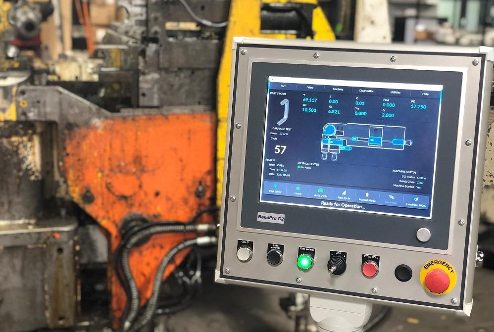
BendPro software offers users of digital servo drives a real-time view of what’s happening in the machine, even remotely.
Recently, we got a call from a manufacturer of hydraulic parts that was losing a couple of hours of production every shift on one of its CNC tube benders: “We can run a few parts, then we get a carriage fault!”
The bender in question is an older machine that was upgraded with a new BendPro G2 control system about six months before that. The business replaced the unit’s old analog servo drive and motors with new digital drives and servomotors from Bosch Rexroth.
On a CNC tube bender, the movement (axis) of virtually every device can be precisely positioned by servomotors, which are controlled by a servo drive. A servo drive is an amplifier that converts the machine’s electrical voltage into a controlled voltage to precisely move a servomotor.
A servomotor provides a signal back to the drive, which monitors its speed and direction. To know which direction and how fast to move, the control system must provide information to the drive. Most CNC benders have at least two servomotors, and an all-electric machine may have 12 or more.
Analog. In an analog servo system, the main control system sends an analog signal that dictates drive speed and direction. The signal may be a low amperage analog one, but the most commonly used systems provide a command voltage, up to 10 positive DC volts or down to 10 negative DC volts (+/- 10 VDC). In theory, if a zero-volt command signal is applied to the drive, the axis should be stationary. If the system supplies +10 volts, the drive should move at full speed in one direction; if -10 volts, it should move at full speed in the opposite direction; if 5 volts, it should move at half speed; and so on.
The drive translates any command voltage provided into a relative speed and direction of the axis. The drive then monitors that voltage to make sure the servomotor is executing the correct speed and direction.
Position and speed feedback also are provided to the control system; the drive may send a signal that emulates the motor’s feedback signal or there may be a second encoder that is monitoring axis position data. The control system uses this feedback to adjust the analog voltage signal to precisely control the axis.
The drive and control systems also must have some additional inputs and outputs to communicate status to each other. The control will send an enable signal, indicating it is OK for the drive to move the axis, and the drive will provide an OK signal that tells the control unit it has not encountered any problems with its internal systems or the motor.
Additionally, as a safety measure, when the control system is not ready for movement, it usually will prevent the drive from moving an axis at all by using a contactor to disconnect the main power source from the drive or provide a break between the drive and the motor.
An additional analog signal may also be tied to the drive to communicate how much of the motor’s available power should be used to make a movement.
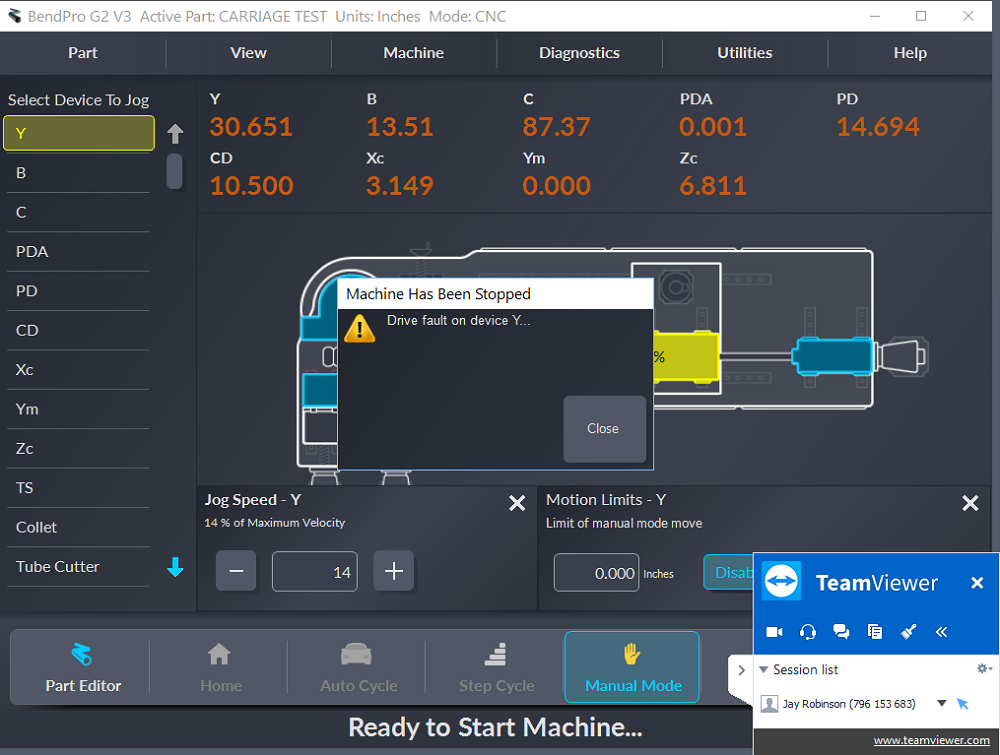
With a drive fault during normal operation, the machine will stop, and a message will appear stating that one of the axes (in this case, the Y axis) is in fault.
Because all this takes place over a series of wires and cables in the machine and control cabinet, analog systems are susceptible to electrical noise, which may cause unintentional movement in the axis. A cut or shorted cable also may transmit unintended voltage to the analog signals or prevent position feedback. In extreme cases, the axis may run away uncontrollably.
When troubleshooting an analog system, a technician should check inputs, outputs, and command signals with a common voltmeter. Most modern analog drives have a small screen that displays a status message showing the condition of the drive. This could be a simple two-letter code or a series of symbols and lights. Most systems also maintain a log of recent faults.
This historical data can prove quite valuable to a technician troubleshooting an analog system. To retrieve historical data, a computer will have to be connected directly to the drive, and the manufacturer’s software used.
Chris Brennan, controls engineer at Current Tech (maker of BendPro tube bending software), said, “Analog drives often just give a generic drive fault signal. To investigate the actual fault often means opening the high-voltage cabinet doors, which for safety reasons is generally not permitted for operators to do.”
Digital. In a digital servo system, the drive still controls the motor speed and direction and receives feedback from the motor confirming that it’s executing the correct speed and direction. However, the command from the control system and feedback from the control system are provided along a digital communication network.
Manufacturers of servo and control systems have developed different protocols and methods for communicating among devices (for example, ProfiBUS, ModBUS, EtherCAT, and SERCOS). They all allow two-way communication between the servo drive and control system, as well as many other devices that may be required.
In a digital system, rather than a voltage or amperage signal being sent by wire to communicate speed and direction to the drive, the control essentially sends a signal that says, “Move to this position, at this speed”, and the drive handles the actual movement of the motor. Position and speed feedback are provided back to the control system along the same digital network thousands of times per second. Because these systems do not rely on an analog signal, they are much less likely to allow unintended movement due to electrical noise or a cut or shorted cable, so there is much less risk of axis runaway.
Because the drive is connected to a digital communication system, much more information can be transmitted back and forth, either directly to the control system or to the drive’s software. During operation, the drive can monitor the motor for critical data such as motor speed, scaled distance moved, actual scaled position, motor temperature, and torque required to make a movement.
Depending on the drive manufacturer and the communication protocols used, a technician can use this data to troubleshoot multiple things going on with a particular axis and may even be able to test motor and axis movement and scaling independent of the main control system.
Typically, you can often load the drive manufacturer’s software directly onto the control system. If you do, a technician can access the entire servo system remotely across the digital communication system without needing a direct connection to the servo drive. With remote connection to the machine, a technician can monitor status, history, scaling, and other system parameters to determine what is causing a particular problem. With a local operator controlling machine movement, a technician can monitor live data from the servo system.
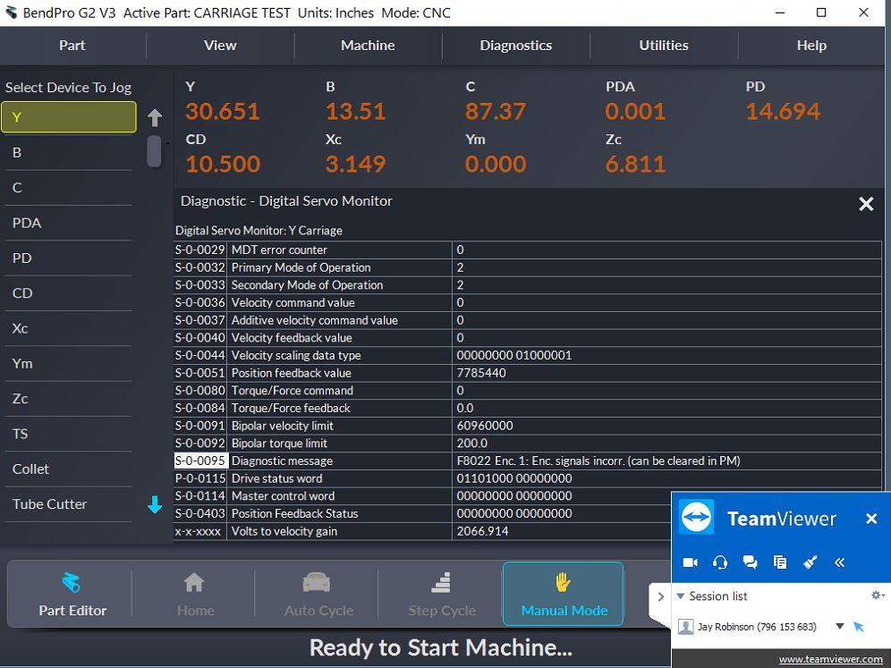
The diagnostic message here indicates that there is a problem with the encoder signal. With an internet connection at the machine, a technician can log in and troubleshoot the bender remotely.
“With digital drives, it is possible for actual fault data to be read and recorded by the control system, meaning primary troubleshooting of the system could occur much more readily, possibly without the need to open the cabinets at all,” Brennan said.
On the bender that could only run a few parts before a carriage fault, an RbSA Industrial technician was able to log on remotely to the control PC running BendPro G2 bender control software and monitor the carriage while a local operator tried to run parts. Generally, while an axis is being moved, BendPro monitors its position and speed, and movement only is allowed if the axis stays within a certain position window.
Eventually, during production, the control stopped the tube bender and displayed a Y-axis (carriage) position error. After faulting this way, the machine could be restarted and make a few more parts, seemingly without problem, before the same error would return.
While logged into the control PC, the technician also logged into IndraWorks, a software package from Bosch Rexroth that allows connection to the servo system over the system’s EtherCAT network. He accessed the drive’s historical fault data and found a series of overcurrent faults.
As a rule, servomotors are rated to run at a specific torque at specific motor speeds, and this is controlled and monitored by the drive. The motor should be able to operate indefinitely at up to 100% of its rated torque. However, a servomotor also may be operated for short periods of time at a higher torque so it can provide short bursts of extra power during certain operations—for example, to accelerate, maintain velocity, and decelerate. If the motor requires more than 100% torque for too long, too much electrical current will be consumed by the drive system, which can cause the drive or motor to be damaged. Before this happens, the drive will stop movement of the axis and put itself into a fault status.
With the operator continuing to try to run parts and the technician remotely monitoring, there were several more position error faults, but after several minutes, rather than position error, BendPro displayed a Y-axis fault. The drive had faulted and communicated that fault status to the control. A quick check in the IndraWorks software confirmed it was again an overcurrent condition, as had been recorded in the fault history. The software pointed to the motor being required to use too much torque for too long.
While monitoring torque percentage, the operator jogged the carriage back and forth along the machine using the manual mode and joystick on the control and saw that (as expected) torque briefly exceeded 100% of rated tolerance during acceleration and deceleration. Then, after several moves along the entire length of the machine, torque leapt over 200%--and not just during acceleration but during unloaded movement. That eventually re-created the overcurrent fault.
As it turned out, one of the linear bearings that the carriage rides on had failed and was causing the motor to work much harder than it should have to position the tube for the next bend, sometimes getting far enough behind its expected position to cause the control to stop the machine with a position error. In turn, that sometimes caused the drive to stop the machine with an overcurrent fault, preventing damage to the motor.
Luckily the manufacturer’s maintenance department had a bearing available and was able to identify and replace the faulty bearing. The machine was back into full production about 20 minutes later.
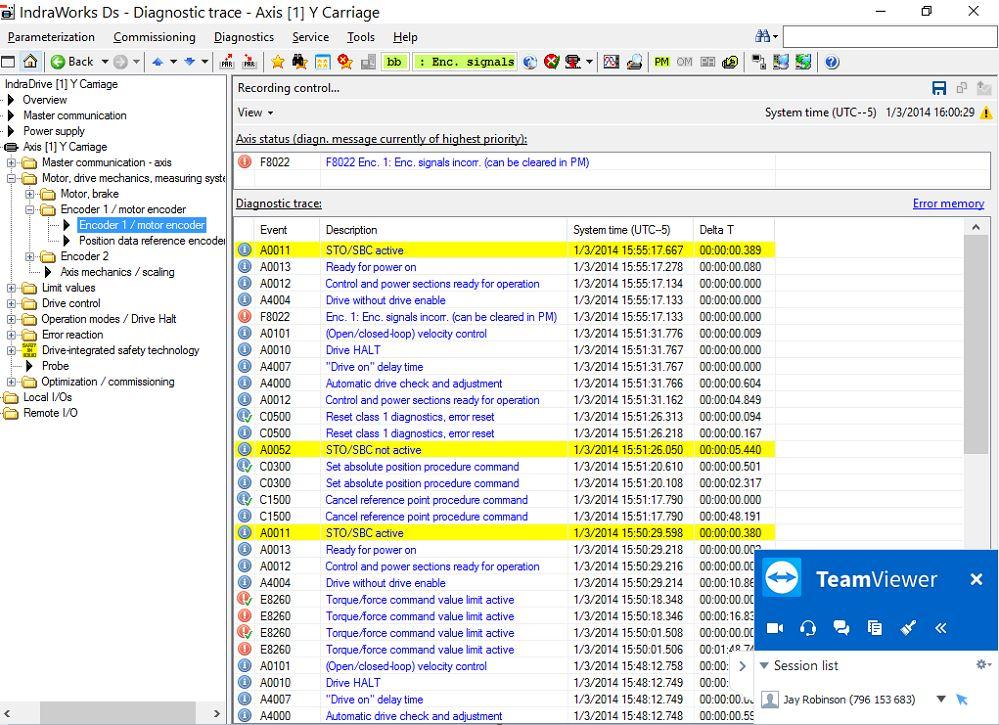
Using Indraworks from Bosch Rexroth AE, a technician can remotely access a drive, as well as its current condition and fault history, without anyone opening an electrical cabinet.


The Tube and Pipe Journal became the first magazine dedicated to serving the metal tube and pipe industry in 1990. Today, it remains the only North American publication devoted to this industry, and it has become the most trusted source of information for tube and pipe professionals.
start your free subscription
Easily access valuable industry resources now with full access to the digital edition of The Fabricator.

Easily access valuable industry resources now with full access to the digital edition of The Welder.

Easily access valuable industry resources now with full access to the digital edition of The Tube and Pipe Journal.

Easily access valuable industry resources now with full access to the digital edition of The Fabricator en Español.
In this episode of The Fabricator Podcast, Caleb Chamberlain, co-founder and CEO of OSH Cut, discusses his company’s...


