


Founder

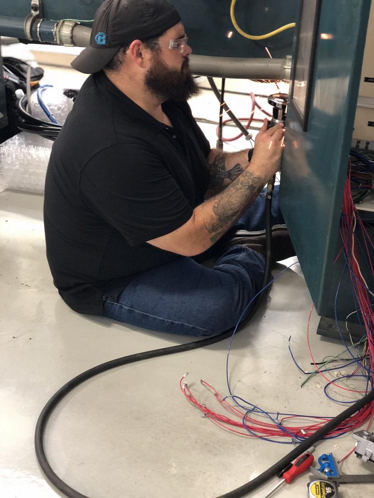
IgorNelson / iStock / Getty Images Plus
The control systems on tubing benders have evolved from relay logic systems, in which a series of relays and switches determined what moved and when, to PC-based systems based on machine logic contained in very specialized software specific to tube bending applications.
Some of the earliest PC-based systems from the 1990s are approaching 30 years of service. Software support and updates from the manufacturers ended long ago, and the hardware running the systems may be more than a decade into obsolescence. If you still have one of these older control systems in production, you are living on borrowed time. These systems will eventually fail and will not be worth repairing.
It is time to upgrade.
When you decide to upgrade the control system on your tube bender, there are many things to consider, and you can help the process along by gathering the necessary information ahead of time.
Existing machine schematics (both electrical and hydraulic) will help define the machine capabilities designed by the OEM and determine what, if any, improvements can be made during the upgrade process. Photos of the machine from many angles also can help you determine the machine’s condition, direction of bend, and if the devices and functions listed in the schematics as optional are actually present and being used. Pictures of data plates on motors and hydraulic valves (or a list of the manufacturers’ names and model numbers) will help you determine if those can or should be reused.
Whatever company installs your upgraded controls likely will have a series of questions and suggestions aimed at helping you get the most possible continued service out of your machine. Armed with the aforementioned information, your service providers will be better able to help you.
CNC benders typically have a minimum of three servo axes (feed, rotate, and bend). They all have some form of position, speed, and direction feedback that the control system uses to precisely position the axis during operation. As a part of the upgrade process, you should determine if the existing servo systems will be re-used, upgraded, or replaced.
Most older electric servos use an analog voltage or amperage signal to control the speed and direction of the axes, and you may be able to keep your initial costs down by re-using these systems. However, analog control systems are more susceptible to unintended movement from electrical noise, and you may also be putting off the inevitable breakdown.
Working closely with your installer, you should determine:
It is possible on some older electric servo systems to partially upgrade the system, replacing outdated drives but keeping existing servomotors. This option has the potential to significantly reduce the cost of upgrading a machine with a large number of electric servo axes or with very large servomotors. In this instance, you potentially get the benefit of eliminating the analog system by upgrading to digital communication between the control and drive.
There are a lot of options when it comes to upgrading the controls on tube bender, but metal fabrication shops shouldn’t let fate force their hand because of fairing to replace an outdated system.
The downside here is that you may still have outdated and unsupported servomotors on your machine. However, many reputable shops specialize in rebuilding and repairing servomotors. Working with your installer, you may find a brand new motor that is an acceptable cross reference and works with the new drive. This should not be very difficult, although lead times may be long.
Most older hydraulic servo systems have an analog servo valve that uses an analog signal to control speed and direction. These systems include an external encoder that uses incremental signals to provide feedback to the control system.
An incremental encoder provides a series of signals (or pulses) that tell the control the axis has moved a specific distance per pulse. The control then counts the pulses to determine distance moved.
However, this does not tell the control the actual position of the axis. To determine that, some sort of homing sequence must be performed to place the axis at a specific position so the control system knows where to start counting. Similar to an analog voltage, the signals from an incremental encoder are susceptible to variation from electrical noise.
As part of the upgrade, you may consider changing the encoder type from incremental to absolute. With an absolute encoder, position can be continuously maintained even when power to the machine is removed. That position is then digitally transmitted to the control, usually eliminating the need for a homing process and greatly reducing the effect of electrical noise on the system.
The servo valve itself may be obsolete, so you should consider replacing it with a new servo valve or more robust proportional positioning valve.
During the upgrading process, you might consider adding several options to your machine.
Safety Devices. While you’re upgrading the control system, it’s the perfect time to look at machine safety. Consider replacing safety mats with laser scanners, which are much harder to bypass or defeat. You also may consider interlocked fencing that prevents machine operation if operators venture into areas where they could be injured if the machine were to move.
Programmable Pressures. Ideally you want the ability to set a specific hydraulic pressure for a hydraulic device. This will control the amount of force applied to tubes in various situations. For example, bending an aluminum part will require much less pressure from a pressure die than the same size steel part.
With programmable pressures, the control system can precisely and consistently set these pressures based on how the machine is programmed rather than by an operator manually adjusting a valve.
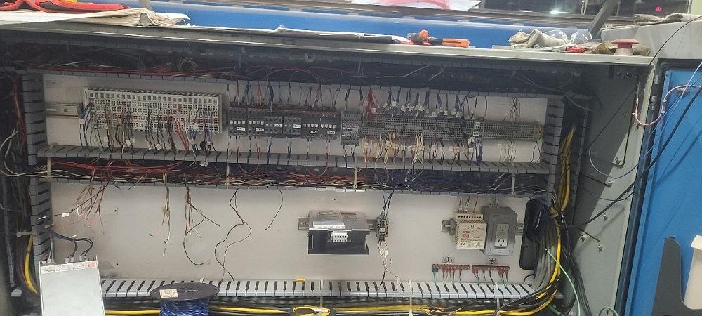
Control cabinets can include more than 1,000 wiring points. Close documentation is highly recommended.
Additional Servo Devices. Replacing certain components with servo devices can enable you to precisely control positions that had to be set manually before. Some possible applications are moving the machine head horizontally to set the correct bend radius, precisely controlling the closed position of a pressure die, or enabling precision control of your pressure die assist (follower) speed so that the PDA can be set to match the speed of the bend arm.
Upgraded Directional Valves. A lot of older systems used 120-V AC signals (the same voltage found in household electrical systems) to fire the solenoid on directional valves. Consider replacing these with valves using 24-V DC valves. By doing this, you may be able to remove a heat- and noise-generating transformer from the electrical cabinet. This also makes a machine safer.
Interface to a CMM. If you have a tube measuring system, new controls may allow you to interface directly to it. Corrections to the part data can be made automatically.
Imported CAD Data. Your new control system may have the ability to open and analyze parts created in common CAD software, creating nominal part data from the model.
Ask your installer what the plan is for tying the new system into the control cabinet and what the expected timing is. Ask for before and after photos of previous upgrades as well.
While it is not necessary to replace every component in a cabinet, understanding what is being replaced—and what is covered should something fail—is very important. Bear in mind that by the time all is said and done, there likely will be more than 1,000 wiring points. Make sure this is well-organized and documented.
Planning a controls upgrade before the existing system dies is the absolute best scenario.
In today’s world, lead time on some components, such as motors and drives, is approaching one year. Waiting until a machine is down to make the decision to upgrade the control system may force you into using existing systems that are beyond their serviceable life to get your machine back into production faster.
Also, new control systems often come with options that may not be apparent until operators start training to use the new system. This adds startup time that you may not want to give away.
While it depends on the machine and which systems are being upgraded or replaced, once power is switched off a machine for new controls, a service provider usually can turn power back on in three or four days. With a day of machine setup and troubleshooting, it is common to have machines back in production in about a week.
However, regardless of how well you have planned, it is not uncommon after the installation has started to find undocumented changes to the machine or its operation—or to find that components that you planned to reuse are not operational. Because of this, plan for two to three weeks of downtime for any upgrade.
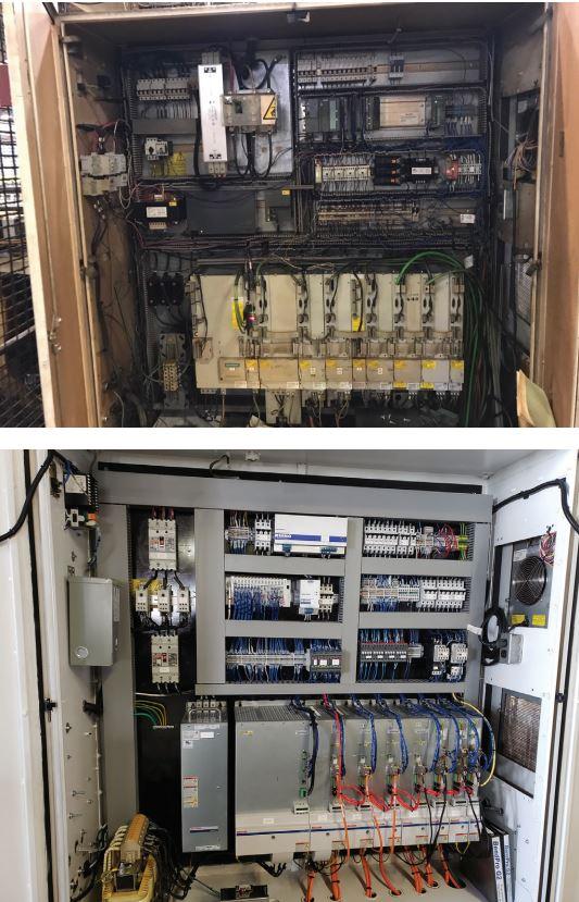
Proactively switching from an old tube bender control system (above) and a new one can mean the difference between merely enduring a couple of weeks of planned downtime and suffering a jolting, unexpected stop to your operation that can last much longer.


The Tube and Pipe Journal became the first magazine dedicated to serving the metal tube and pipe industry in 1990. Today, it remains the only North American publication devoted to this industry, and it has become the most trusted source of information for tube and pipe professionals.
start your free subscription
Easily access valuable industry resources now with full access to the digital edition of The Fabricator.

Easily access valuable industry resources now with full access to the digital edition of The Welder.

Easily access valuable industry resources now with full access to the digital edition of The Tube and Pipe Journal.

Easily access valuable industry resources now with full access to the digital edition of The Fabricator en Español.
In this episode of The Fabricator Podcast, Caleb Chamberlain, co-founder and CEO of OSH Cut, discusses his company’s...


