


Founder
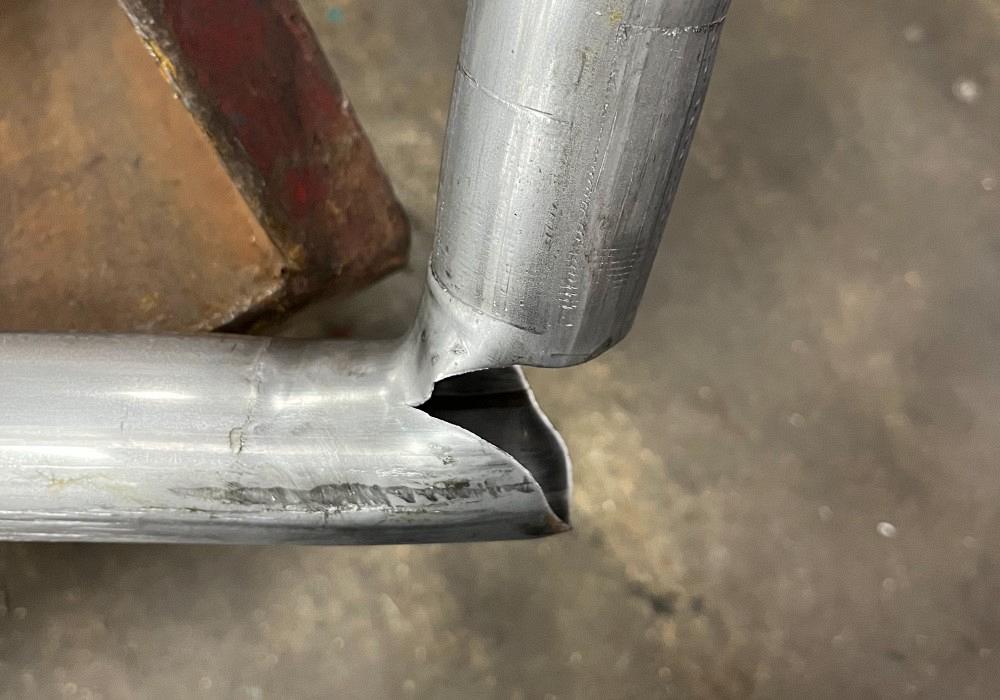
Finding the cause of this torn tube required digging deep into the tube bender and visually observing everything that was happening.
I recently visited a manufacturer that was having trouble consistently making quality parts with its CNC tube bender.
This was a challenge. Sometimes the part would wrinkle badly on the inside of the bend; sometimes the part would break on the outside of the bend. And sometimes there would be three, four, or more bends in a row that were perfect. With no change to the tools or machine setup at all, the parts were consistently inconsistent!
In the best of circumstances, this was not an easy part to make. It was 2-in.-OD aluminized tubing with fairly thin walls (0.049 in.), bent on a 2-in. centerline radius with a short grip length. However, this was a manufacturer experienced in making these parts with very experienced personnel setting up and operating the machine—and an excellent maintenance crew.
I was lucky enough to learn tube bending from setup, operator, and maintenance personnel like this who make these difficult parts every day. They really know their parts, machines, and tooling. When one of these guys tells me, “I don’t know what is going on,” it’s serious.
After watching a couple of parts run and seeing the inconsistency, with the operator’s help we decided to start fresh as if the part were being set on the machine for the first time. At the same time, we verified the operation and position of the all-electric machine’s 10 axes, and we went through the part settings in the control system. We noted that the carriage position was off a little and that the pressure die assist (PDA) was about 1/8 in. behind where zero should have been. We also noted that the bend arm’s zero was a little behind where it should have been.
If you have ever set up a tube bender for production, you know that several things are hard to set up consistently. One person may go about it differently from another, and that can cause differences in the way a part runs each time it is set up. Mandrel position, wiper die position and rake, clamp die position, and pressure die position are just a few things that easily can be set up differently by two different operators—or even the same operator setting up for the same part at different times.
One of the advantages of using an all-electric bender, on which every axis that moves is precisely positioned by the control system, is that a lot of those setup variables can be minimized. But even with benders that are not all-electric, practices can be put in place to help ensure consistent setup. These practices, if applied consistently by setup personnel and operators, will reduce the amount of scrap when changing from one part to another and can greatly reduce changeover time.
The manufacturer in this case had great processes in place to make sure the tooling setup was repetitive and consistent. However, that relied on consistency in the machine’s positions.
Tangent Variation. Tangent on a tube bender is an imaginary line perpendicular to the path of the tube as it enters the bend die. This is where bending occurs. A slight change in bend arm position will change the apparent position of the bend die’s tangent relative to the tube’s path, and that could make the position of the wiper die and its rake—when compared to the clamping section of the bend die—different from the actual rake relative to the path of the tube being bent. This will cause the apparent position of the mandrel to differ from the position when measured from actual tangent.
Bend Arm. If the bend arm is too far out of position, the act of clamping—rather than movement of the bend arm—will start the bending process. If this happens, the tube may fold instead of bend.
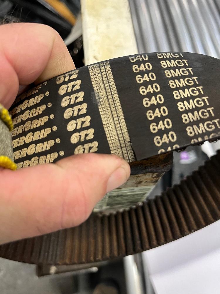
Eventually it was discovered that a torn belt was hopping over a tooth in a sprocket, which caused operators to overcompensate multiple times when they reset other components in the tube bender, causing breakage in the tube.
Pressure Die Assist. The PDA moves the pressure die forward during bending so that it follows the path of the tube during bending. On machines with a PDA, the speed of this axis can be matched to the relative speed of the tube or may be set up to push on the tube to minimize wall thinning on the tube OD. Too much wall thinning results in the tube splitting.
The PDA’s zero theoretically sets the face of the pressure die directly on tangent. However, different machine manufacturers and tooling designers may add a small clearance, putting the face of the pressure die behind zero so there is enough room for the clamps to close without colliding.
We reset the carriage, PDA, and bend arm positions. The customer reset the bend tooling, and we made a couple of test bends. A few minor adjustments later, the machine was back in production. Everyone was happy, and I started packing my tools and filling out paperwork.
Just as I started to walk away, there was a “pop” sound from the machine. The part finished—it still looked good and fit the gauge. However, I decided to stay and watch a few more parts. After another few minutes, there was another pop, but the bender was still turning out good parts.
After a few more minutes, though, there was a third pop. This time the part no longer fit the gauge, and the bend quality was not quite as high as before. We stopped production and double-checked the tooling setup. Everything looked exactly as it did when we made the first good part. We ran one more part. This time, we heard another pop. The outside of the tube ripped at every bend!
We took another look at tooling setup, and everything still looked the same. So, we verified the axis positions yet again. The carriage and bend arm were still correct, but the PDA was again about 1/8 in. behind where its zero should have been.
The PDA on this machine was servo-driven, and with the tight-radius part being manufactured, the company relied on its push quite a bit to minimize the amount of material thinning along the outside of the bend. This PDA was mounted to a reducer, and a very strong timing belt rotated the nut on a ballscrew, which positioned the PDA. We removed the covers and visually inspected everything, but we saw no evident problems.
Then, with the covers off, we ran another part. We heard another pop, and then we saw it: The timing belt jumped over a tooth on the sprocket!
We found a small rip in one edge of the timing belt. When it made its way around the sprocket under the load needed to make the part, the small rip loosened the tension on the belt just enough that it was able to jump a tooth. Every time this happened, the PDA returned to a position slightly further back. This made it appear as if the bend arm was farther out than it actually was.
Over time, this had been enough to cause the problem. Thinking the bend arm was out of position, because of the too-large gap between the pressure die and clamp die, the company’s maintenance crew had reset the bend arm position relative to the PDA, moving it slightly behind zero. This made it appear the carriage was out of position forward, so its position was also slightly changed. Every time the crew made these changes, the machine was able to go back to production for a while. But then the whole process was repeated until the three axes were so far out of position that even when the crew followed its setup procedures, the wiper and mandrel dies could not effectively do their jobs.
Fortunately, the company had a spare belt on hand. We were able to change the belt, reset the PDA position, and put the machine back into production.


The Tube and Pipe Journal became the first magazine dedicated to serving the metal tube and pipe industry in 1990. Today, it remains the only North American publication devoted to this industry, and it has become the most trusted source of information for tube and pipe professionals.
start your free subscription
Easily access valuable industry resources now with full access to the digital edition of The Fabricator.

Easily access valuable industry resources now with full access to the digital edition of The Welder.

Easily access valuable industry resources now with full access to the digital edition of The Tube and Pipe Journal.

Easily access valuable industry resources now with full access to the digital edition of The Fabricator en Español.
In this episode of The Fabricator Podcast, Caleb Chamberlain, co-founder and CEO of OSH Cut, discusses his company’s...


