


Founder
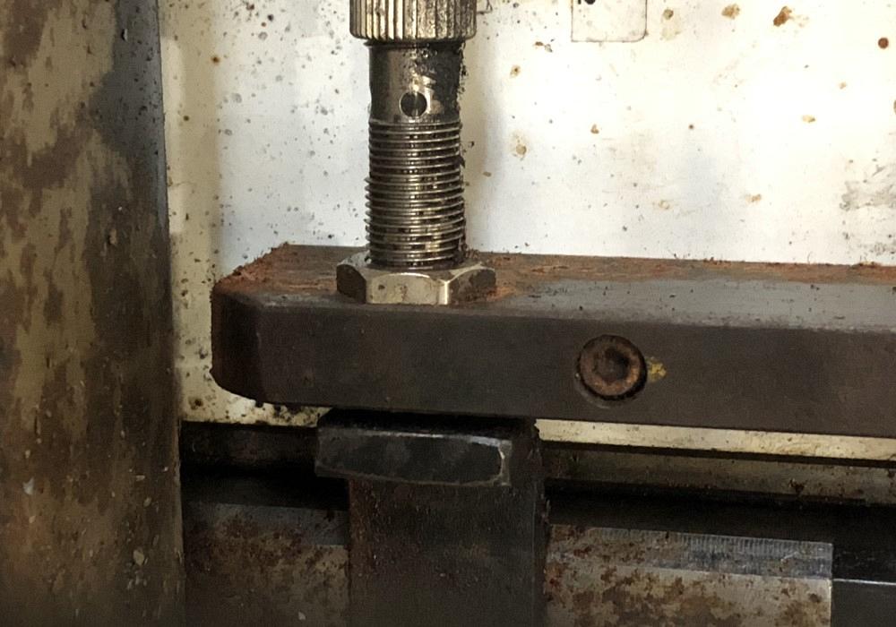
A home switch provides information to a control system to place an axis into a desired position. This type of switch can be very accurate, but it also suffers performance degradations when exposed to extreme temperature or humidity or too much wear, if used in a mechanical application. RbSA Industrial
Editor’s Note: This is the first of a series of tube bending machine troubleshooting articles from Jay Robinson of Robinson Bender Services and Automation Inc.
“We can’t run in auto!”
This was the somewhat desperate phone call I received from an exhaust manufacturer. One of the electric servo axes on his CNC tube bender was going into fault during homing. Without completing the homing process, the control system would not let the operator select automatic operation. Tube bending production was effectively halted.
Troubleshooting this type of problem requires an understanding of how each axis on the machine is homed.
For safe operation of a CNC tube bender, the control system must know the position of anything that moves on the machine—clamp die, pressure die, bend arm, carriage, collet. Its process to determine the correct position of each moving device is called homing.
During homing, directional (also known as Bang-Bang) devices are moved to a position where they are most likely to be clear of all other devices. For example, the collet, clamp die, and pressure die will be moved to their fully open positions.
The control can use many different methods to determine the position of a device. In its simplest form, the control system moves a directional device for a certain period of time, assuming once that time has passed, the device has fully moved to the desired position (usually the full length of its movement).
The control system also might use a series of switches to determine the position of a directional device, but this can be imprecise. For example, a pressure die might have an open switch and a closed switch but a total travel of several inches. If it is halfway into that travel, neither the open nor closed switches will be on, and the control no longer knows where the die is. The control will have to move the die to one position or the other to correctly determine its location.
On a servo axis, the control system uses precise position feedback to determine position, direction of travel, and velocity. That information is then used to control the axis. While almost anything that moves on a CNC tube bender can be designed to be servo-controlled, the most typical are the bend arm, the carriage for feeding the tube, and tube rotation.
The feedback for a servo axis is provided by an encoder, which relays movement information to the control system in the form of counts. When the machine is first set up, the technician determines the number of counts per unit of movement. On a linear axis, this might be counts per inch or counts per millimeter; on a rotary axis, it’s counts per degree of rotation.
Encoders can be absolute or incremental. An absolute encoder stores its count data regardless of whether the machine is on or off, or even if the axis is moved while power is off. When the machine is on, the control system uses this stored data to determine the actual position of the axis, without necessarily having to go through a new homing process. An incremental encoder provides counts during movement and has no data storage. The control system must determine the actual position and then maintain the position data by continuously keeping up with the change of counts in either direction of travel. During homing, the axis is slowly moved to a known position, then the control maintains all position data based on the change of counts.
With an incremental encoder, the known position for a servo axis can be determined a few different ways:
A CNC tube bender can have a mix of servo axes that have incremental or absolute encoders, and each servo axis may use a different method for determining position. For example, the bend arm may home by stall verified by a switch, and the carriage may use a marker pulse after moving to a switch near the end of its total travel. During the process of homing, each axis is moved in a specific sequence to make sure the movement of one axis does not damage another. The physical design of the machine determines the safest sequence and the direction of movement. Directional devices usually move to their fully open positions, absolute axes may move to a safe position, and incremental axes move through their respective homing process using switch, stall, or marker pulse. Once the entire sequence is complete, the machine is homed.
On the machine that would not complete its homing sequence and thus couldn’t run in automation operation, the problem was an axis that moved vertically using an electric servomotor and provided feedback to the control via an incremental encoder. Its position during homing was determined by finding a marker pulse after movement to a switch near the end of its possible downward travel. During homing, the vertical axis was the last in the sequence to be moved to find its home position, but its drive would eventually display that the motor was being overloaded, causing it to go into a fault. Because it was the very last axis in the homing sequence, we were confident it was the only cause for homing not to complete.
Working remotely with the machine operator, we explained the actions the machine should make during homing of the vertical axis: move down until it passed in front of a proximity switch, stop for a brief second, then move upward a short distance while it searched for the marker pulse. Once it found the marker, the control would assign the correct position and homing would be complete. The exhaust manufacturer was able to find the switch easily by following the axis path of travel.
After clearing the overload fault on the drive (we had to power the entire machine down and back on), we determined that the axis could be manually jogged upward. When homing was attempted again, as expected, the axis moved downward toward the travel limit, but instead of stopping when it passed the switch, it continued moving down until it reached the end of its travel, eventually hitting a hard stop. Knowing to expect the axis to stop and change direction when it passed in front of the proximity switch, the fast-thinking operator stopped the machine by hitting the emergency stop button, preventing another motor overload.
As it turned out, the switch was not signaling the control that the axis was near the end of its travel, so the control never reversed direction to start its search for the marker pulse. One of the nuts holding the switch in place had vibrated loose, and the switch had moved. After a simple adjustment of the switch position and a machine rehome, the manufacturer was back in production.


The Tube and Pipe Journal became the first magazine dedicated to serving the metal tube and pipe industry in 1990. Today, it remains the only North American publication devoted to this industry, and it has become the most trusted source of information for tube and pipe professionals.
start your free subscription
Easily access valuable industry resources now with full access to the digital edition of The Fabricator.

Easily access valuable industry resources now with full access to the digital edition of The Welder.

Easily access valuable industry resources now with full access to the digital edition of The Tube and Pipe Journal.

Easily access valuable industry resources now with full access to the digital edition of The Fabricator en Español.
In this episode of The Fabricator Podcast, Caleb Chamberlain, co-founder and CEO of OSH Cut, discusses his company’s...


