


Founder
Oren Kfir / iStock / Getty Images Plus
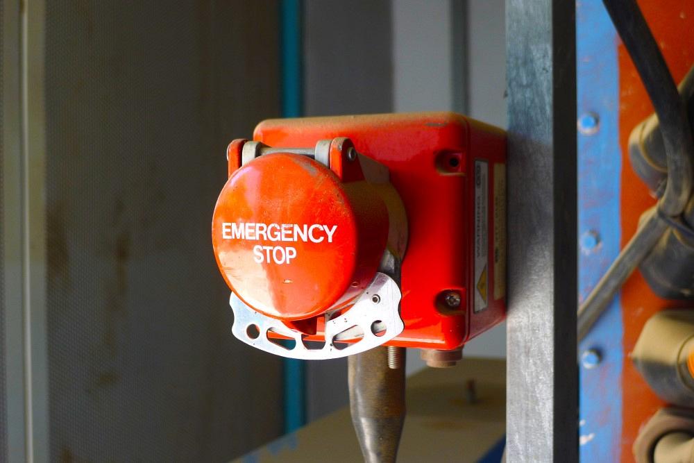
The bender won’t start! We checked all the buttons, but the display still shows it is in the emergency stop position.
The dreaded E-stop.
We probably get more calls about E-stops than any other part of a tube bender. This may be the simplest circuit in the machine—it has a very clear function—but troubleshooting it can be a nightmare.
At its most basic, the E-stop circuit is intended to stop all movement on a machine. However, a properly designed E-stop circuit also prevents the machine from starting in an unsafe condition. While the function of the E-stop has not changed, how it is integrated into machinery has changed significantly over the past few decades.
In today’s CNC machines, the E-stop is really a stand-alone system that operates independently. While it sends a signal to the control system to tell it the status of the E-stop, it also may receive a signal monitoring the state of the control.
An E-stop system has a safety relay (or safety PLC) that performs three major functions:
E-stop buttons should have dual circuits that provide a continuous electrical path to specific inputs on a safety relay. The safety relay monitors the continuity of the circuits and cross-checks to make sure the wires have not been cut or shorted together. The safety relay then will turn on or off several relays that remove available control voltage from the various systems on the machine if an unsafe condition is indicated. The relay also monitors the state of those systems to prevent machine startup in a potentially dangerous situation.
We still occasionally run across older machinery with only a single circuit that relies on the control system (not safety rated) to stop the machine. The danger in this setup is a lack of redundancy: A failed relay, bad programming, or a host of other factors could prevent the E-stop circuit from stopping the machine.
Standards now require tube benders to have safety-rated and redundant hardware that can stop the machine. The control system’s software may monitor the state of the hardware and also turn off outputs. But in an unsafe condition, this is secondary to the E-stop system.
To troubleshoot an E-stop system, you should understand what it means to have an open or closed circuit.
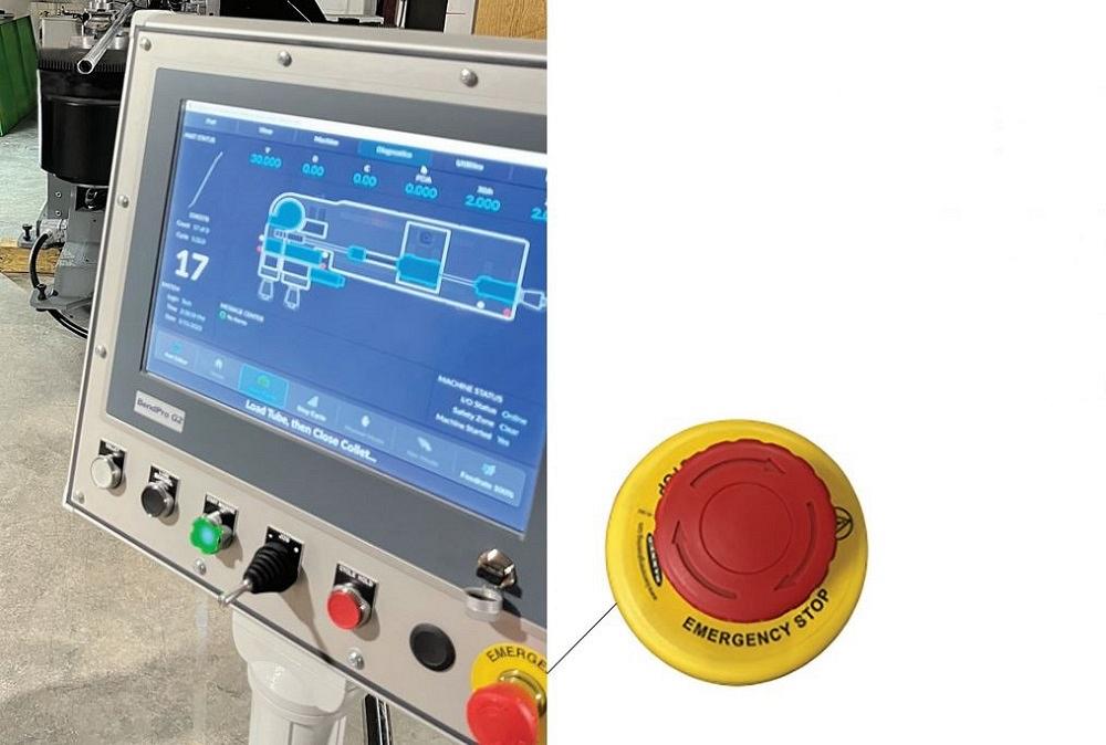
A metal fabrication shop knowing how to respond to a tube bender in the emergency stop state means first knowing the circuits, voltage, and relays in the machine.
A single piece of wire, one end to the other, is a closed circuit. When properly connected, electricity can pass along the wire. If you cut the wire in the middle, the circuit has been opened and electricity can no longer pass through. If you connect the cut ends to the terminals of a button, the button effectively reconnects the wire, once again making it a closed circuit.
Now, if the button is normally open, connecting it to the cut ends of the wire will leave the circuit open until the button is pushed, which closes the circuit. If the button is normally closed, connecting it to the cut ends of the wire will return the wire to its closed state until the button is pushed, which then disconnects the ends of the wire and opens the circuit.
In either case, if releasing the button returns it to where it started from, it is referred to as “momentary.” If releasing the button leaves it in the state it went to when pushed, it is referred to as “maintained” and will require some user action—a pull or a twist—to return it to its normal state.
Almost without exception, modern machines have at least one E-stop button that is a normally closed and maintained button, with two circuits that remain closed in the normal (safe to run the machine) state. A push of the E-stop button will open the E-stop circuits, and they will remain that way until the button is returned to its normal condition.
An E-stop button may have other circuits that are either normally open or normally closed that communicate the state of the button to the control system, but they don’t have the primary purpose of stopping the machine. There may be other components, such as gate switches or axis overtravel switches, in the E-stop circuit and their normal state may be either open or closed, but they will always be in a closed state when the machine is safe to run. This way, if a cable or wire that is part of the E-stop circuit is inadvertently cut and left in an open state, the machine fails to a stopped (safe) state.
The voltage that travels along the two closed circuits in an E-stop button’s portion of the system depends on the design of the two circuits and the safety relay used.
Typically, both circuits have 24 VDC, or one circuit is 24 VDC and the other is 0 VDC.
In a system with two 24-VDC circuits, if the two wires are cut and short to each other, the circuit might appear to be in a safe state, regardless of the status of the E-stop button or other components in the system. In a system with both a 24-VDC and 0-VDC circuit, if the wires are cut and short together, one of the channels on the safety relay will have the wrong voltage, which will put the relay into an unsafe state and stop the machine.
However, if the 0-VDC wire is cut and grounds to the machine body, the safety relay could still detect two good circuits. However, a press of the E-stop button will still stop the machine, as the 24-VDC circuit still becomes opened.
In newer systems, the E-stop relay or safety PLC sends a series of timed pulses along the two wires, with each channel being unique. It then monitors for the same series of pulses to return along the closed circuit. In this scenario, if the wires are cut and shorted together, the wrong series of pulses will return—or if they short to ground, no pulses will return at all. This will the stop the machine.
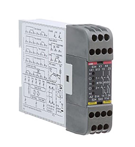
FIGURE 1 A typical safety relay commonly used for E-stops that has five lights on the front. The center light is confirmation that the relay has power.
A relay is a device that controls one voltage based on the status of another voltage. In the case of a safety relay in an E-stop circuit, the controlling voltage is the series of buttons and switches intended to stop the machine if an unsafe condition occurs. The controlled voltage supplies the outputs that turn various other systems on or off.
For example, an output from the control system may turn on the hydraulic system, and the supply voltage to that output will be controlled by the safety relay. In this way, even if the control system is trying to turn the hydraulic system on, or the output in the control system fails in an “on” position, the E-stop relay will prevent it from starting by removing the supply to that output.
Once a machine has been stopped, the E-stop relay monitors the status of several other devices to make sure the whole machine is in a condition that is safe to start. This is often accomplished by looking at the status of a series of normally closed switches from each device within the circuit that resets the E-stop relay. If one of those devices is in a state making it unsafe to start the machine, the E-stop relay cannot be reset and the machine cannot be restarted.
While it is not strictly necessary to have accurate wiring schematics to troubleshoot the E-stop system on your machine, they will be incredibly helpful. Having the manufacturer’s manual of the safety relay in your E-stop system is also very helpful. Most can be downloaded for free from the manufacturer’s website.
The first step in troubleshooting an E-stop system is to look at the E-stop relay itself. Most have a series of lights that will guide you in your next troubleshooting steps.
Figure 1 shows a typical safety relay commonly used for E-stops that has five lights on the front. The center light is confirmation that the relay has power. The top and bottom lights (In1 and In2) indicate the status of the E-stop buttons. The second and fourth lights indicate the status of the outputs that turn on the circuit and power the various devices in the control system. If all five lights are on, the relay has power, both circuits from the E-stop buttons are good, and the relay has reset, turning on control voltage to the machine. This is a normal status, and from the perspective of the E-stop system, the machine is ready to start or may already be running.
In Figure 2, if all five lights are on, control voltage is being provided through the relays marked MCR and MCR2. However, for example, if the center light and only the top light (In1) are on, only one of the circuits is good in the part of the system with the E-stop buttons.
Looking at the schematics using this same relay, the good circuit of the button system starts from the E-stop relay at wire 401, goes through the normally closed console E-stop, moves through an output that enables control, and then returns to the relay as wire number 403.
The part of the circuit that is not providing a light (In2) starts as wire 200 (which is 0 volts), goes through a second control-enable output, passes through the second set of normally closed contacts on the console E-stop, and then returns to the relay as wire number 400. Each connection along the path should be checked; without both parts of the circuit complete, the machine cannot start.
As another example, if the center light and the top and bottom lights are on but the second and fourth lights are off, there is likely no need to check the E-stop buttons and switches because the relay already has determined that part of the E-stop system is good. In this case, if the machine will not start, you need to look at the reset/monitoring circuit because the relay has not been reset. This starts with wire 124; proceeds through the normally closed contactors for the motors 1M, 5M, 6M, and 2M; then also goes through normally closed contacts for MCR and MCR2. This then supplies the normally open reset button.
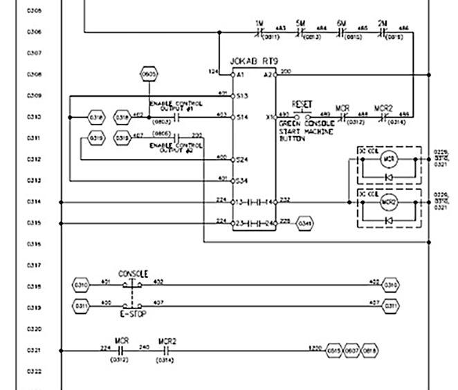
FIGURE 2 If all five lights are on, control voltage is being provided through the relays marked MCR and MCR2. However, for example, if the center light and only the top light (In1) are on, only one of the circuits is good in the part of the system with the E-stop buttons.
In the normal state, the machine is off, and each device is safe for the machine to be started. With a push of the reset button, the E-stop relay will reset, voltage will be applied to the control outputs, and the machine can be started. If any of these devices do not return to their normal state after the E-stop button has been pressed, voltage will not be supplied to the reset button, and the machine will not start. If this happens, check each connection and confirm that each device has turned off properly.
If your machine uses a safety PLC, it may also use a series of lights or have a small display that indicates its status. The safety PLC also may serve a dual purpose, monitoring both the E-stop system and other safety systems, such as floor mats or safety scanners.
However, the principle will be the same: A series of buttons and switches will indicate if the machine is not safe to be on, it will prevent the machine from starting if all of the systems do not return to a safe state after stopping, and it will prevent control voltage being supplied to the control system outputs until it is reset.

The Tube and Pipe Journal became the first magazine dedicated to serving the metal tube and pipe industry in 1990. Today, it remains the only North American publication devoted to this industry, and it has become the most trusted source of information for tube and pipe professionals.
start your free subscription
Easily access valuable industry resources now with full access to the digital edition of The Fabricator.

Easily access valuable industry resources now with full access to the digital edition of The Welder.

Easily access valuable industry resources now with full access to the digital edition of The Tube and Pipe Journal.

Easily access valuable industry resources now with full access to the digital edition of The Fabricator en Español.
In this episode of The Fabricator Podcast, Caleb Chamberlain, co-founder and CEO of OSH Cut, discusses his company’s...


