


Vice President of Sales
Drawing has long been an integral part of the metal production and tube fabrication process. An operation that changes a mill product’s characteristics, drawing can change the inside diameter (ID), outside diameter (OD), surface finish, and mechanical properties to prepare the material for fabrication.
The heart of a drawing operation is the draw die. The die’s success or failure is tied to manufacturing performance, which is related to cost. A poorly designed die can be worse than having no die if it produces nothing but scrap.
Many articles published about drawing have focused on drawing theory and die design. Industry experts such as Dr. Roger Wright, Dr. Horace Pops, and Tom Maxwell have made great strides in research in these areas and have helped to advance the industry by spreading their knowledge, yet the published literature is short on die failure analysis. Examining how dies fail turns into an exercise in learning about best (and worst) practices in die design and use.
Understanding tribology—how the material, lubricant, and tooling interact—is crucial to discovering the causes of production failures. Knowing the broad and fine points of tribology, and doing some detective work, can help you analyze draw die failures and lead to improvements in how the die supplier designs them.
The drawing process applies across the board—it’s used for wire, bar, and tube; for a multitude of shapes; and essentially for any material, from run-of-the-mill carbon steel used to make simple products to pricey alloys for jewelry. Although the examples here in run the gamut, all contain lessons for companies that draw tube.
The basis for every carbide tool is a preform, a semiformed part made of sintered carbide powder that die companies use for making draw tooling. The common standard sizes, available in R designations (R-5 to R-17), run from 0.625 to 4 inches OD. Die companies depend on preform quality as they grind and polish the rough outer surface of the tool. Purchasing a poor-quality preform results in wasted time and resources in finishing. Die companies take a loss when the preform requires extra work to polish it, and their customers take a loss when the tool fails in production.
What contributes to a high-quality preform? The primary factor is sintering, the process that transforms pressed carbide powder into a solid piece. Time, temperature, and pressure are the critical parameters, and they require careful control during this process. These parameters are based on material grade and part size. Inadequate sintering can lead to various metallurgical defects such as porosity, large grain structure, and insufficient carbon (eta-phase).
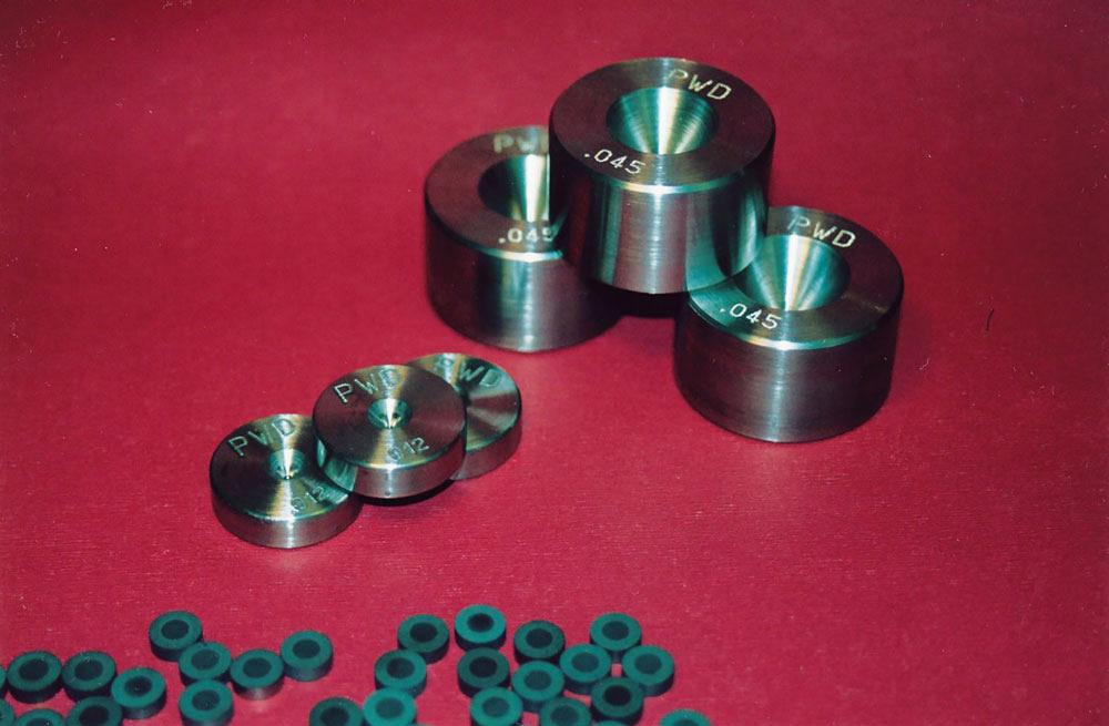
Sintering Case Study. An engineer at a large rod mill provided an experimental die that failed prematurely. She believed it failed because the application was wrong—she thought the draft was too extreme for the die. However, in this case, the insert had a major circumferential crack about one-third of the way down the approach angle (see Figure 1). The insert was too small for the draft, and because the diemaker started with an insert that was undersized, the die’s wall wasn’t as thick as it needed to be. It was too thin to withstand the stresses of the draw. This die design may have worked for draw-ing copper or aluminum, but since it was used on stainless steel, it failed.
Size wasn’t the only problem. A material analysis, performed by a metallurgical lab, was inconclusive about the material grade because the sample was too porous. The lab tech stated that the carbide was either poorly sintered or underpressed, but that he believed it was the former. Poorly sintered carbide doesn’t allow the substrate and binder components, tungsten and cobalt (or nickel), to mesh properly, reducing the part’s structural integrity (see Figure 2).
The analysis identified three reasons that this die failed:
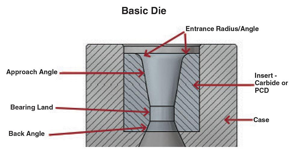
Figure 1
A basic draw die comprises a case and a carbide insert. If the die is designed well, the approach area will bear the brunt of the drawing pressure. Also, the case and the insert will have substantial contact area, which enables the case to act as a heat sink.
The two basic parts of a carbide die are the case and the insert (see Figure 1). The case serves two functions: it provides mechanical support, and it absorbs heat from the insert and passes it along to the die block. Some die blocks are water-cooled to provide even more heat-absorbing capacity.
The efficiency of heat transfer is a matter of contact area. If the contact area between the case and the insert is insufficient, most of the heat generated by the drawing process is absorbed by the
insert, and eventually it overheats and fails. The carbide insert should be centerless- or rough-ground to provide more consistent contact with the case than the insert would have in the rough-cored state.
One way to join the insert to the case is to drop the insert into the case and peen the case’s top edge over to secure the insert. This method isn’t commonly used, and dies constructed in this fashion typically fail.
In dies larger than R6, 0.710 in. OD, common practice calls for heat-shrinking the insert into the case. This is accomplished by designing the insert and the case so that the case’s ID is smaller than the insert’s OD at room temperature. Heating the case causes it to expand to the point that its ID exceeds the insert’s OD. The insert goes into the case and as the case cools, it contracts and clamps down on the insert, providing significant support and maximum heat transfer capacity.
Substandard Die Construction Case Study. Often a draw die exhibits more than one failure mode, although a thorough analysis might reveal a single failure mode that exhibits multiple problems. One case involved a die that had a major circumferential crack and wasn’t fully contained in the case. About half of the die was protruding from the case. Measurements revealed that the case ID was tapered, with a difference from bot-tom to top of 0.003 inch.
The insert’s OD was 1.185 in. The amount of necessary heat-shrink was roughly the same as the case’s taper. After the die was put into use, the insert failed where the support was inadequate.
It’s usually difficult to determine how the insert was installed in the case. Only after dissecting the tool and taking some measurements can a troubleshooter come to a conclusion. In this case, it seemed that the die failed because of poor construction.
When a draw bench operator has a drawing problem, the most common reaction, practically a reflex, is to blame the die. A root cause analysis occasionally reveals a die problem, but most often the trouble originated elsewhere.
Clues to the trouble might be sitting in plain sight around the die area, or they might be lurking around the draw bench anywhere upstream of the die location; it’s a matter of looking at all of the hardware, determining how it was intended to function, and comparing that to how it really does function.

Figure 2
Poorly sintered carbide (left) is characterized by pores or voids, which appear as black spots in a photomicrograph. These are weak spots in the matrix that allow cracks to propagate. Properly sintered carbide (right) has a much more uniform appearance: a mix of white and gray areas, but no black. This reflects a thorough meshing of tungsten particles with the cobalt binder. Photos courtesy of General Carbide.
Of course, it’s rare for any system to run trouble-free for extended periods of time. Everything needs routine maintenance, troubleshooting, and repair. In drawing operations, troubleshooting starts with a close look at the die, but the troubleshooter needs a little help. Establishing the die’s orientation in the die block often is of critical assistance. The draw bench operator performs an invaluable service when he marks the 12 o’clock position on the die when he installs it in the die block.
Mechanical Failure Case Study. A case of wire-drawing dies that suffered from short service life showed the importance of equipment maintenance.
The initial clues indicated a problem with die alignment. The entrance of the die had a wear-ring high on one side at the 12 o’clock position. The opposite side of the die showed no contact by the wire until a heavy wear ring appeared low in the approach angle, near the bearing at the 6 o’clock position. Rather than moving along horizontally, the wire came in high and exited low. This condition indicated an alignment issue.
Although this customer hadn’t established the 12 o’clock position for this die, that didn’t matter in this case. An inspection of the die block revealed little chance of die misalign-ment as long as the block was clear of debris before the draw bench operator installed the die.
The next suspect was the wire feed angle. The last pulley—the one that fed the wire into the die—had a deep groove in it. It was clear that the wire had caused this groove and traveled in it, and thereby it fed into the die at an angle. Instead of traveling horizontally, the wire travel was pitched, creating an inconsistent wear pattern through the die’s approach angle. The customer replaced the pulley, adjusted it to the correct position, and thereby solved the problem.
Variations in hot-rolled material can wreak havoc on draw dies, but they don’t have to. Understanding the specific dimensions of the raw material, and the variations in those dimensions, enables the die designer to develop a die with features that can work with misshapen feedstock.
Poor-quality Draw Stock Case Study. One troublesome application was a 1⁄16-in. draft on a rectangular hot-rolled bar that was to finish at 1 by 1.250 in. The corner radius in the approach angle and bearing of the die were about 0.020 in., with each corner at 90 degrees. However, the feedstock had only one corner that was close to 90 degrees, so only one corner fit with the die; the other three corners of the bar stock made contact with the die’s flats. During the draw, the corners of the bar stock dug carbide particles out of the die. This buildup on the bar stock acted as an abrasive as the draw progressed and gouged material out of the die’s corners near the exit, further degrading the die’s structural integrity, leading to cracks in the corners.
A new die design used recessed tapered, or conical, corners (see Figure 3). This design delayed the point of contact in the corners until the bar was nearly on top of the bear-ing. In other words, at the entrance of the die, the bar’s flats contacted the die’s flats, and the bar’s corners made no contact with the die. The flow of material through the recessed conical corner of the die helped to blunt the sharp corner of the bar and mini-mize the damage in the corner of the die. The new design lasted three times longer than the old design.
Draw dies often are categorized by the cross section at the exit: round or shaped. Round is a category by itself because the design is relatively simple and the stresses are distributed across the die’s circumference consistently. Anything other than round needs a much more thorough analysis of how the die is designed and manufactured.
The optimal way to make a shaped die is to start with a preformed blank prepared for electrical discharge machining (EDM), which is a carbide disc with a small through-hole in the center. The EDM process uses multiaxis slides to transition the approach angle from round (or a shape) at the entrance to a shape at the exit. The die’s design uses the approach angle and back angle to create the desired shape and to maintain the bearing length.
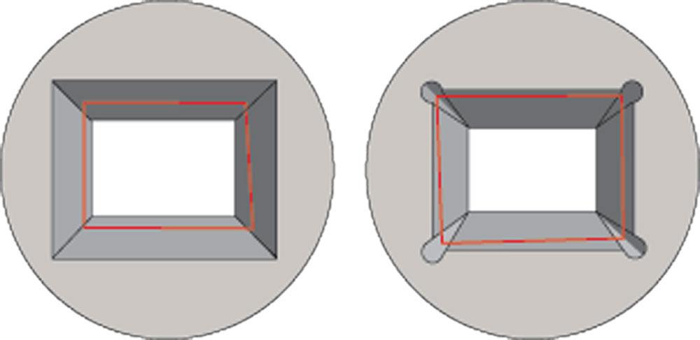
Figure 3
The red line in the drawing on the left indicates a bar that is out of square, with the corners of the bar making contact on the flats of the die. The drawing on the right shows that same bar in a die with recessed conical corners; this shows how the flats of the bars will make contact on the flats of the die, thereby eliminating the corners of the bar digging into the flats of the die.
A low-cost strategy for die design for a shaped product is to start with an R-series insert and use the EDM process to cut the shape into the bearing area and then polish it. This works in some cases, but the die usually doesn’t last as long. Using the bearing to create the shape puts too much stress on the bearing. Also, the process creates undulations in the die bearing land because the approach angle or back angle (or both) don’t have transitions. Some areas of the wire feedstock are under more tension than others, which may distort the wire from its desired form.
Flawed Die Design Case Study. A die intended to create the shape of ski goggles—imagine half of a numeral 8—lasted just a few months. It didn’t take long to determine that the die design was based on a standard R-series insert and relied on the bearing to do the forming. The resolution to this problem didn’t involve making a new die, but rather reworking the existing die, machining the approach angle and back angle to do the forming process, thereby lessening the stress on the bearing.
The reworked die lasted much longer than the original, but the cost of reworking it actually exceeded the price of the original die. Also, the customer also had to deal with another cost: The production time lost while the die was reworked.
In every drawing application, the approach angle’s length is critical. Too little approach length concentrates the drawing pressure over too small an area, leading to a mechani-cal failure. It also compromises the lubricant’s ability to prevent metal-to-metal contact. Excess pressure squeezes the lubricant out, leaving the metal surfaces prone to galling and scratches.
Insufficient Lubrication Case Study. A hex-to-hex drawing application resulted in cracked dies and scratches on the feedstock’s surface. The draft was 1⁄16 in., and the final dimension was 1.250 flat to flat.
An analysis revealed two issues. First, the raw material had two sharp opposing corners and four dull ones; the die had six sharp corners. Second, the carbide insert was about 1⁄2 in. too short.
The assessment was that the two sharp corners were making contact with the die just before the dull corners did, thus concentrating draw pressure at those two points. The resolution involved a new die design, one with recessed conical corners as described in the poor-quality draw stock case study. In addition to preventing the sharp corners from digging into the flats, countersunk corners disperse the pressure inside the die cavity, allowing the lubricant to flow between the workpiece and the die.
Also, the new design had an additional 1⁄2 in. of approach, providing a better wedge-gap in the approach angle. These design changes likewise helped to spread out the pressure, reducing the tendency to displace the lubricant.
All draw dies fail eventually. Good design, proper construction, proper use, good lubrication, and occasional maintenance help you get the most out of your investment—and these practices help to keep the draw bench up and running—but this doesn’t mean that a die can last forever. Every die will fail sooner or later.
If troubleshooting reveals no clear failure, congratulations! The die designer made a die that matched the application well, you took good care of the die, and it simply wore out. If you do detect a failure, look for clues, but don’t stop with everything you see in front of you. You may have seen a similar failure in the past, so giving a little thought to previous troubleshooting experiences—jogging your memory—might yield faster and more thorough results.
David Rascati is the vice president of sales for Premier Wire Die, 1712 Dividend Road, Fort Wayne, IN 46808, 260-496-9300, premierewiredie.com, dave@premierwiredie.com.
The author expresses his gratitude to:


The Tube and Pipe Journal became the first magazine dedicated to serving the metal tube and pipe industry in 1990. Today, it remains the only North American publication devoted to this industry, and it has become the most trusted source of information for tube and pipe professionals.
start your free subscription
Easily access valuable industry resources now with full access to the digital edition of The Fabricator.

Easily access valuable industry resources now with full access to the digital edition of The Welder.

Easily access valuable industry resources now with full access to the digital edition of The Tube and Pipe Journal.

Easily access valuable industry resources now with full access to the digital edition of The Fabricator en Español.
In this episode of The Fabricator Podcast, Caleb Chamberlain, co-founder and CEO of OSH Cut, discusses his company’s...


