


Global Bar and Tubular Products Manager
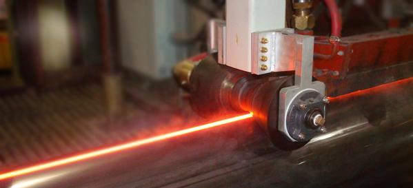
Normalizing small-diameter pipe often is a matter of heat-treating the entire cross-section, but for one specific application, this is particularly wasteful. The tube, in this case, runs nearly seven miles, so great care goes into the design of each piece of equipment on the normalizing line to ensure it doesn't generate any scrap. Images provided
Countless applications use metal tubing, but reusing tubes isn't a common practice. After it's affixed, attached, fastened, or installed, that's usually the end of it. However, a growing practice for a few downhole applications in the oil industry is the use and reuse of small-diameter coiled steel tubes.
The purposes are nothing new. Well operators do frequent visual inspections, dropping a length of tubing outfitted with a camera into the well's borehole. They also use lengths of tubing to drop tools into wells to carry out various maintenance tasks, inject nitrogen or treatment chemicals to promote flow, and open or close valves to connect or isolate sections of the well. Tubing is also used for cleanout operations and to run electrical cables to machines such as submersible pumps.
Conventional operations involve a series of tubing lengths up to 48 ft. joined with couplings. Needless to say, this is cumbersome and labor-intensive, both in the insertion and retraction phases. Much faster is the practice of using an extremely long length of coiled tubing.
Making a long tube and annealing it so that it can withstand repeated coiling and uncoiling is straightforward in principle. However, as with most tube or pipe operations, this sort of thing needs great care. These days, a length of coiled tubing for downhole operations can run nearly seven miles. Nobody wants to make a mile (or six) of tubing destined for the scrap heap because something went wrong.
Uncoil it and use it. Coil it up and move it to the next well. Uncoil it and use it. This can't last forever. Every time steel changes shape, it undergoes stress. In this case, the metal can undergo only so many cycles of coiling and uncoiling until it becomes too fatigued to withstand any more deformations; eventually, splits will appear. Making this tube is an expensive proposition; getting the longest service life from it is a matter of proper heat treating, annealing, or normalizing.
Any sheet, plate, bar, or billet of metal looks like a homogenous, continuous mass. However, it's not that simple. When steel is heated, the atoms of iron take on a specific structure. If the processing temperature is less than 1,674 degrees F, it takes on a body-centered cubic structure. Imagine the eight corners of a cube—eight evenly spaced iron atoms—with one more point in the center, and you can imagine this structure. At higher processing temperatures, depending on the percentage of carbon, it undergoes a transformation to a face-centered cubic structure, which has 14 iron atoms.
Depending on the temperature, one of these two microstructures appears all throughout the steel, one cubic shape after another, forming a lattice. A vast lattice makes up a grain of the steel. As the metal remains at critical temperature, the grains grow until they come into contact with other grains, which is where grain boundaries form.
Grain growth is halted by cooling the steel rapidly. Cooling it sooner rather than later results in relatively small grains, which are associated with hardness and strength; the downside is that hardness equates to brittleness. Cooling it later allows the grains to grow larger, which results in a softer material that forms more easily than a fine-grained material.
So, the steelmaking process is a matter of controlling the processing temperature and the amount of time it spends at that temperature, and then cooling it rapidly. . These steps, along with adding a bit of carbon while it’s molten—usually less than 2% by weight—and some other elements determine the steel's properties.
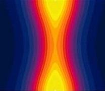
Figure 1. A high-frequency induction heat-affected zone typically looks like an hourglass. This results from heat generated at the OD by the induction coil and at the ID by the impeder.
More and More Heat. When a long, narrow strip of this material is fed into a tube mill, the process starts over where the two edges meet to make the weld seam. The weld heat is introduced to the steel by an induction coil that surrounds the OD and an impeder that directs the flow of current on the ID. The metal along the two edges becomes red hot, nearly returning it to the state is was in back at the steel mill. The tube then is doused with coolant to achieve the rapid cooling necessary for profitable production rates.
Throughout most of the tube profile, the microstructure is unchanged. The weld heat isn’t distributed throughout the rest of the metal (the parent material), so it doesn't get hot enough to change appreciably. The weld heat is concentrated along the weld seam and in the area immediately adjacent to it, where it becomes red-hot and undergoes rapid cooling. In the heat-affected zone (HAZ), the area near the weld seam, the grains had little time to grow, so the material has a fine grain structure. The material in the HAZ is more brittle than the material elsewhere around the circumference. This is why anyone who bend tubes and pipes always tries to align the weld seam with the neutral axis of the bend.
On a tube intended to be coiled and uncoiled (bent and straightened) repeatedly, any fractures—which occur between grains along the grain boundaries—will develop in the HAZ long before they develop in the parent material.
Heating the material again, and cooling it slowly as it was cooled at the steel mill, is the key to starting over and allowing the grains to grow until they return to normal size. Reducing the severity of the grain size differential, or eliminating it altogether, is an annealing process commonly known as normalizing.
Understanding the Heat Profile. It's worth noting that the heating process used for welding and the heating process used for normalizing are fundamentally different processes. Although both rely on induction, welding applies heat via the induction coil (on the OD) and by use of the impeder (at the ID); normalizing uses an inductor only. Because of this difference, the heat profile is different. In welding, the heated area through the cross section takes the shape of an hourglass; normalizing creates a heat profile in the shape of a letter U.
On large diameters of tube or pipe, a common practice is to seam-anneal the material by heating it only in and near the HAZ. Using induction heating—the same process that makes the weld on most weld mills—to focus the heat along the weld seam isn't difficult. After locating and orienting the inductors appropriately, it's a matter of matching the heat to the line speed to carry out the necessary amount of annealing to soften and normalize the material in the HAZ.
On small diameters, it’s common to anneal the entire circumference. This wastes quite a bit of the energy when the target area that requires normalized is only the weld HAZ, but it's difficult to get around it on small diameters. However, the traditional way isn't the only way; several years ago, research and a field implementation proved that it is possible to normalize just the HAZ on tubes that measure less than 2 in. dia.
Doing so efficiently and effectively hinges on three main factors: the distance between the inductors and the tube's surface, the alignment of the weld seam and the inductors, and tracking the weld seam to maintain the alignment.
Keeping the Proper Coupling Distance. Using induction heating efficiently is a matter of keeping the induction coils as close to the surface as possible, and the standoff distance in this application ideally is not more than 0.200 or 0.300 in. If the standoff distance is greater than 0.300 in., the efficiency drops exponentially.
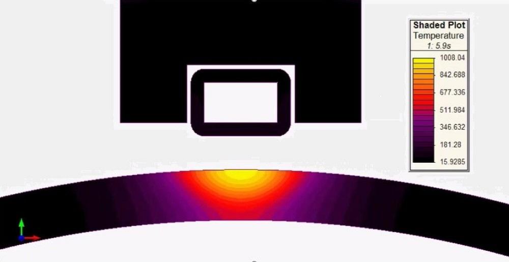
Figure 2. Because normalizing can't access the ID, the sole heat source is at the OD, and the normalizing heat profile is shaped like a letter U.
The problem with keeping a minimal standoff distance is that a variation or disturbance on the mill can decrease the gap, which risks creating a short circuit where the tube makes contact with the inductor. Considering the amount of electrical power in this application, a short-circuit is a potential disaster for the tubing and the induction coil. Ceramic standoff wheels can help to prevent contact. Still, the wheels are just single points of contact spaced along the induction coil's length, so maintaining the proper standoff distance is still challenging on smaller diameters.
Another problem is that the induction process generates magnetic lines of flux that create vertical forces called Lorentz forces. Research has shown that magnetic lifting forces can exert nearly 90 lbs. of upward force on predominately 2.0-in.-dia. and smaller tubes. This wreaks havoc on the tube's dimensional consistency, leading to a distorted tube and adding to the possibility of short circuit between the induction coil and the tube.
Seam Width. Typically, a single inductor of a specified width is used for a range of tubing sizes. Knowing the width of the weld HAZ is necessary to design induction coils that work as efficiently as possible. They have to cover enough of the tube's circumference to normalize the entire width of the HAZ to the ID of the tube. Still, if there is too much overlap between the weld HAZ and the inductor width, electrical energy waste increases. In addition, on smaller diameters, excessive overlap causes heat to saturate the tube's circumference, increasing the steel’s elasticity and rendering it more susceptible to distortion.
Finite element analysis (FEA) can determine the width of the HAZ in the annealing process, but this is too big a tool to use for every project. In addition, developing an FEA is a time-consuming and expensive process. A slightly less exact method, but a much faster one, is to cut and etch an as-welded tube sample to determine the actual width of the HAZ. A heat distribution profile graph of the normalizing process then can be produced that allows the prediction of the seam annealing HAZ.
Seam Tracking. A third element in induction efficiency is maintaining the inductors' location relative to the seam. Ideally, the weld seam and the inductors are perfectly aligned, centered at the 12 o'clock position, but the seam does tend to wander left and right as the tube moves through the mill. In most cases, the seam deflects less than +/- 7.5 degrees, so an orbital coil positioner that moves a total of 15 degrees covers the typical deflection.
Quite a bit of engineering goes into making very long lengths of tubing and doing so efficiently.
First, these tubes don't have a single wall thickness. The first section down the hole has the lightest wall; subsequent sections have heavier walls to provide more strength to support the increasing amount of weight.
Second, while the process could use full-body annealing, this is too wasteful. In some common tube applications—say, a few hundred lengths of 20 ft. each—a full-body anneal would make sense because setting up a custom-made inline normalizing system with a seam tracker and an orbital unit is an engineering-, capital-, and time-intensive undertaking at best. For a small contract, the return on investment isn't likely to materialize. However, for a program that involves making hundreds or thousands of flexible steel lines that run for miles, the full-body anneal wastes far too much energy, and a custom annealing line can be justified.
Third, when developing a normalizing system that anneals several diameters and wall thicknesses, the smallest sizes get more heat saturation around the circumference, thus increasing the metal's plasticity. The Lorentz forces come into play and can cause some distortion.
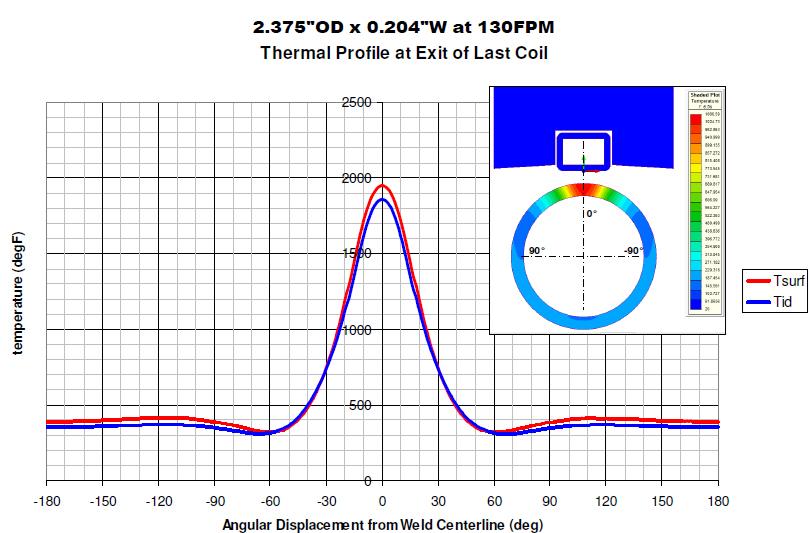
Figure 3. As annotated on this chart, angular displacement refers to the heat distribution of an annealing line and the resulting heat-affected zone. The center of the chart, at 0 degrees, represents the weld seam center, which is the center of the annealing coil placement. For this diameter, the heat distribution is about +/- 60 degrees from center.
These forces can be countered by using a larger number of smaller inductors. In a properly designed system using this principle, the total amount of heat the inductors generate is the same, but each generates less magnetic flux, thereby generating less vertical force, thereby reducing the distortion.
Using these inductors, known as twin series inductors, allows the use of additional steel standoff wheels, which are placed between the inductors. In other words, whereas a conventional system has ceramic standoff wheels, this system has those and two additional modes of protection against short circuits: less vertical lift from the magnetic flux, and additional guide wheels located between the induction stations.
Depending on the level of expertise and the time put into designing such a system, two competing normalizing lines can differ quite a bit in their layouts. For example, a conventional system designed more or less along traditional principles might use four separate induction stations. In contrast, a more sophisticated, updated approach can result in a system that does the same amount of work with just three induction stations, conserving floor space and energy. This equates to less equipment on a smaller footprint operating more efficiently.
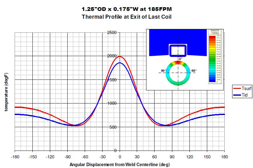
Figure 4. The heat distributions vary. Although similar to the heat distribution in Figure 3, this chart shows a wider heat distribution as measured in degrees of rotation (+/- 75 degrees) on a smaller diameter. To be effective, a normalizing system must be designed to capture the widest heat profile of the pipe to be produced on this mill.

The Tube and Pipe Journal became the first magazine dedicated to serving the metal tube and pipe industry in 1990. Today, it remains the only North American publication devoted to this industry, and it has become the most trusted source of information for tube and pipe professionals.
start your free subscription
Easily access valuable industry resources now with full access to the digital edition of The Fabricator.

Easily access valuable industry resources now with full access to the digital edition of The Welder.

Easily access valuable industry resources now with full access to the digital edition of The Tube and Pipe Journal.

Easily access valuable industry resources now with full access to the digital edition of The Fabricator en Español.
In this episode of The Fabricator Podcast, Caleb Chamberlain, co-founder and CEO of OSH Cut, discusses his company’s...


