


Senior Editor
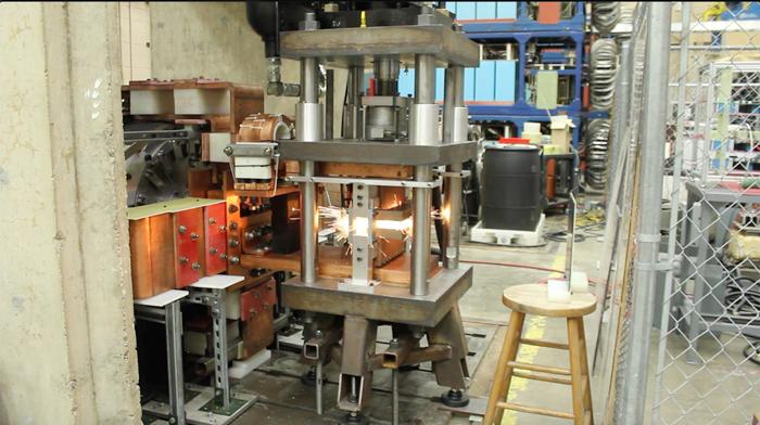
A press fixture holds workpieces as a homopolar generator sends a pulse of energy to complete a large weld in seconds.
Imagine a technology that could weld a circumferential seam of the Trans-Alaska Pipeline in less than three seconds. It turns out the technology, an ultrahigh-power forge-resistance process called homopolar-generator (HPG) welding, has been around for decades.
In the 1980s researchers at the Center for Electromechanics at the University of Texas at Austin (UT-CEM) worked to perfect the pipe welding process in a joint industrial program with major oil companies, looking for a way to streamline welding for offshore J-lay pipeline construction. They came close, nearly perfecting the joint prep and welding parameters to produce a clean weld within a few seconds.
The pipe being tested wasn’t as big as the Alaska pipeline, but the process would have been straightforward enough to scale up. Alas, HPG welding never caught on, in part because of equipment costs.
But technological advancements have changed that cost equation. Today a decades-old technology is being dusted off, tested, and perfected again—this time for bridge welding. If UT-CEM researchers and industry partners prevail, HPG welding could transform the world of industrial, structural, and pipe fabrication.
Most modern generators, everything from power plant turbines to the alternator in your car, are heteropolar, producing a current by passing a conductor by different magnetic fields in opposite directions and alternating from one to the other—hence the term “alternating current.”
A homopolar generator has one source of an electromagnetic field, which spans from the center of a spinning disc to the rim. Producing direct current, the generator’s polarity hinges on the disc’s direction: spin it in one direction and you get a positive polarity; spin it in the negative direction and you get a negative polarity.
Being solid metal, that spinning disc has very low electrical resistance, or impedance, which made it particularly valuable for researchers at UT-CEM, including Associate Director Raymond Zowarka. “Because the metal disc has incredibly low resistance, if you have a way of getting power out of that spinning disc, then you can draw tremendous current.”
The spinning disc builds voltage, and thanks to the low impedance, a relatively few volts can produce an immense amount of current. Just a few dozen or hundred volts can be converted into a burst of more than a million amps.
That burst, or pulse, of power is what made it so useful for the researchers at UT-CEM, a center launched in the 1970s to tackle the opportunities of pulsed power. Early work analyzed pulsed-power capabilities in capacitors, batteries, and rotating machinery. “Our studies concluded that rotating machinery was more power-dense and could cover a wider range of applications,” Zowarka said, “and so that’s what we pursued, researching pulsed power and rotating machinery.”
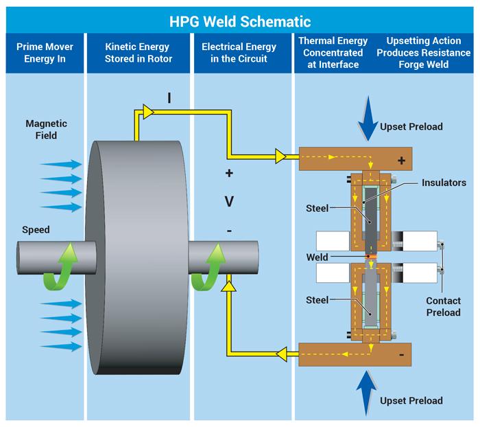
HPG welding uses pulsed power generated by the conversion of kinetic energy from the rotor into electrical energy and, finally, thermal energy at the weld.
Some of UT-CEM’s early work included the design of machines that could provide the immense power that tokamaks (torus-shaped devices that confine hot plasma) required for experimental nuclear-fusion generators. Over the years UT-CEM’s teams pursued myriad homopolar research avenues, doing work funded by grants and industry partnerships. For instance, the center did work for DARPA to develop homopolar generators for railguns, weapons that shoot projectiles at seven times the speed of sound—and need a large pulse of power to do it.
The research also included what Zowarka called “Friday afternoon experiments.” On many Fridays the team pursued a range of experiments in a quest to answer a basic question: What else can we do with the HPG machine?
On a Friday afternoon in the 1980s, one of those experiments involved welding. As Zowarka recalled, “We took two pieces of round 1080 steel barstock. We literally blacksmithed two copper busbars, hammering them around these two round bar samples. We pressed them together with a fixture made out of heavy spring-loaded washers, discharged the homopolar [energy] through it, and lo and behold, it welded those two pieces of steel together. We were probably passing something around 500,000 amps through the interface.”
The area of highest resistance, at the weld interface, immediately turned orange and then white-hot as the metal heated beyond forging temperature. Pressure in the fixture forced the bars to forge. After welding, all that was left was a little bit of upset metal that, once scraped off, revealed a clean weld line around the circumference of a single, now longer piece of barstock. The team had performed its first HPG weld, a resistance weld on steroids.
That first machine’s rotating metal disc was 3 feet in diameter and about 1 ft. thick. “It had the weight of a small Volkswagen,” Zowarka said, “and it spun at 4,000 RPMs. We had black tape on half of the rotor shaft and white tape on the other half. And when it was spinning, all you’d see is a gray blur.
“Within one second, the shaft came to a dead stop. It was a classical electromechanical conversion. We had converted all that kinetic energy, that small Volkswagen spinning at 4,000 RPMs, and put it into the weld. The magnetic field passing through the rotor starts interacting with every atom in the rotor that’s carrying current. Every electron attached to every atom feels the stopping force at the same time. Each atom passing current is grabbed by the magnetic field, converting all that rotational kinetic energy into electrical energy. That’s where that huge burst of current comes from, and all that electrical energy goes into the weld.” The Lorentz force at its most brutal, such energy can fuse a massive amount of metal nearly instantaneously.
After those initial experiments, the team began welding all kinds of metal, including a variety of mild steels, stainless steels, chrome-moly steel, aluminum, even tungsten. “We tried just about everything,” Zowarka said, “and it’s all in a big NSF [National Science Foundation] report published in the early 1980s.”
Eventually came the joint industry project with oil companies looking to streamline pipeline welding. Much of that work focused on fine-tuning parameters, including workpiece alignment and load forging pressure, as well as the weld preparation.
The weld prep was particularly important, because engineers were aiming to eliminate as much postprocessing as possible, especially on the inside diameter of the pipe. A butt joint configuration requiring little to no prep would have been ideal—just like the butt joints in those barstock tests during those Friday afternoon experiments.
Nevertheless, HPG tests for pipe welding revealed that the pipes still needed to be beveled to a particular land thickness for optimal results. A thin land concentrated the current flow, aided welding efficiency, and directed the forging action to minimize the amount of remaining flash that needed to be removed. For pipe welding, the less flash that had to be removed from the ID, the better.
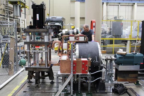
An engineer sets up an HPG welding machine. The large round enclosure houses the rotating disc that produces a massive pulse of current.
The incredible speed of HPG welding makes it sound as if it would make business sense, even if the equipment were expensive. But as Scott Pish, research engineer at UT-CEM, explained, those few seconds accounts for welding time only. It still takes time to position and align the workpieces, and flash still needs to be removed after welding. “Most of the time is spent loading, aligning, and prepping.”
Even so, that time still is quite minimal, especially when you consider how long it takes to weld the pipes manually. Even removing the flash after welding doesn’t take long; a simple scathing tool will do—no grinder necessary. So why isn’t HPG welding a common pipe welding technology today? Why didn’t the process take off?
Much of it had to do with the cost of the equipment, which required hydrostatic bearings to ensure consistent rotational motion. “That made the rotor run on a film of high-pressure oil,” Pish said. “And we used those for years,” adding that those bearings also made the machine expensive.
But by the mid-1990s, bearing technology had evolved substantially. “By then the Japanese had developed ceramic bearings, which have now become very common,” Zowarka said. “These ceramics break the magnetic path.” This means that the machine no longer needs all the auxiliary components it once did, which also means that the machine cost is a fraction of what it was.
“That reduced the cost by a factor of four,” Pish said. “And that’s using inflation-adjusted dollars.”
All this research has set the stage for the latest potential homopolar application: bridge welding. UT-CEM answered a call from the U.S. Department of Transportation for proposals to weld bridge flanges out of high-performance steel, an application now dominated by submerged arc welding (SAW).
Working with engineering consulting firm Koo and Associates, the team has tested workpieces with HPG welds 6.5 in. long and 1 in. thick. Like the pipe welding application before it, this bridge welding application does require weld preparation, this time a K-bevel for a double-V joint geometry with a 0.5-in. land.
“Once it reaches forge temperature, [the bevel section] flattens, and material extrudes out as flash,” Zowarka said. “This gets rid of any impurities and oxides that were on the surface. They’re naturally driven out of the weld zone.”
Researchers have worked with a Houston metallurgy firm to study micrographs of the resulting weld. “The metallurgists tell us that the grain size looks very good at the weld interface,” Pish said.
The latest experiments incorporate a kind of homopolar-style postweld heat treatment. After the welding cycle, the HPG starts rotating the disc again to heat the workpiece and slow the weld cooling.
“We’ve seen immense improvement in factors like tensile strength,” Zowarka said, adding that these latest welds have undergone destructive and nondestructive testing, including various bend and tensile tests. “The tensile specimens are excellent.”
The welds have passed all tests as dictated by industry welding standards like the AWS D1.5 Bridge Welding Code, save one: the Charpy V-notch test for toughness. As of this writing, the center is working on a potential solution: a new fixture with actuators that could disengage the copper contacts after welding. Currently the fixture incorporates bolted copper contacts that aid welding, but afterward they act as a heat sink, drawing heat out of the weld zone quickly.
“We feel that if we have those actuators that can pull those copper contacts back, the weld will cool much slower,” Zowarka explained. “This might bring us over that final hurdle during this phase of our research.”
Shortly after winning the project from the DOT, the UT-CEM team visited a local structural and industrial fabricator to observe current practices, including the weld prep, the SAW process itself, and the postweld grinding and finishing.
The team analyzed an application involving four large welds placed on a 150-ft.-long workpiece. “Using SAW, it took the shop just over two days,” Zowarka said. “We did a time study for the welding, and we found that to load the large workpieces into our fixture, power up the homopolar machine, discharge it, and make the weld, it would take [the HPG welding process] less than a day. And they told us that cutting out an entire day in the production process would be extraordinarily significant for them.”
HPG welding does require large machinery, so it’s obviously suited for in-house welding. Hauling a welding system to the field wouldn’t make sense—in most cases, that is.
“This is designed to be an in-house process,” Pish explained, “but at the same time, we are discussing the potential of railcar-mounted machines powered by diesel engines. These systems could weld railroad rail in the field.” He also said that the previous pipeline project involved a system that could be transported to an offshore J-lay pipeline construction platform.
“The DOT is interested in us commercializing this technology,” Pish added. “So we’re now in the process of trying to identify potential applications and industries that might be interested in this. We have a machine, the bus work, the press that preloads the joint. It’s a system that’s essentially ready to go to try a variety of welds.”


The Fabricator is North America's leading magazine for the metal forming and fabricating industry. The magazine delivers the news, technical articles, and case histories that enable fabricators to do their jobs more efficiently. The Fabricator has served the industry since 1970.
start your free subscription
Easily access valuable industry resources now with full access to the digital edition of The Fabricator.

Easily access valuable industry resources now with full access to the digital edition of The Welder.

Easily access valuable industry resources now with full access to the digital edition of The Tube and Pipe Journal.

Easily access valuable industry resources now with full access to the digital edition of The Fabricator en Español.
In this episode of The Fabricator Podcast, Caleb Chamberlain, co-founder and CEO of OSH Cut, discusses his company’s...


