


Best practices for the best press brake bending performance
Develop good setup sheets, backgauging practices, and a strategy for dealing with material variability
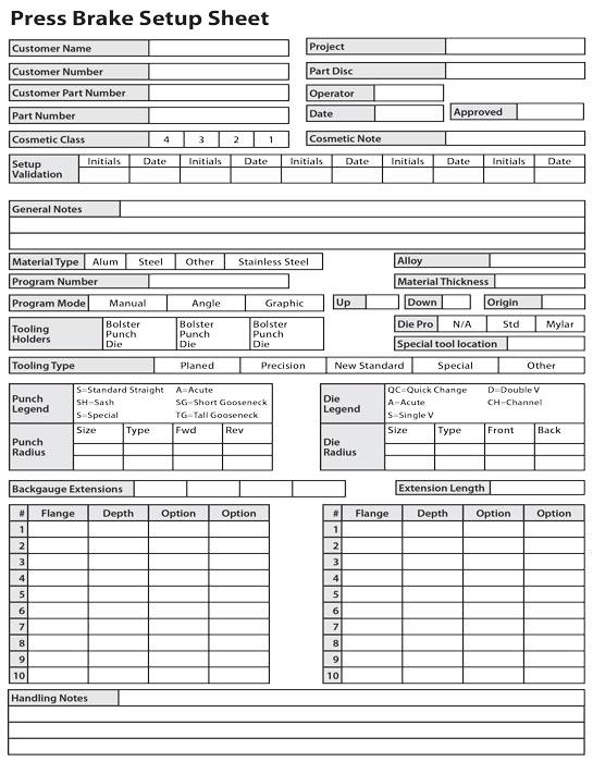
Figure 1
The front of this setup sheet includes space for customer and in-house data, validations, tooling type and direction, and basic program data.
Question: We are a medium-sized manufacturer that produces electrical switching cabinets and control systems. Many of these are quite large, the size of small buildings when assembled. Some may have a dozen or more panels in the assembly.
Each unit is similar, but each job is different, so setup sheets are not part of our process. We air-form galvanized steel. Our press brake operators use European-style precision-ground tooling, with a small punch nose radius across all parts. Because our panels are the same size and shape, our most significant variable is the material gauge change from one project to another.
It seems that almost every project ends with us having to build a one-off custom panel to adjust for the compounded dimensional error across the multiple sections that comprise a completed unit. As you might imagine, having to build a custom piece each time is affecting our bottom line dramatically. Do you have any suggestions on how we can avoid this?
Answer: Based on what you have just described, I have several suggestions that can improve your operations. Three of these stand out more than the rest: setup sheets, backgauging practices, and ways to deal with material thickness variation.
The Absolute Necessity of Setup Sheets
In shops that primarily air-form with their press brakes, everyone must use the same tooling to produce a given part. The die opening establishes the inside radius and, by extension, the bend deduction.
This makes setup sheets an absolute necessity. Having everyone working off the same setup sheet for a particular job, you can make it mandatory that every operator use a certain established die set with a given work order, material type, and thickness.
Implementing a setup sheet program will improve your consistency and quality, with everyone producing the same formed part dimensions from a given flat blank. Figure 1 is an excellent example of a setup sheet. You’ll want to modify it to meet your own needs, but it gives you a place to start.
Tool selection is the heart of the setup sheet. Have engineering obtain a list of available tools from your operators. You mentioned you have many parts that are the same except for the material thickness. Considering this, you have two options. The first is to use a single die set across all versions of a part and change the bend deduction based on the inside radius floated in that die set. The second is to use a die opening as close to perfect as possible for forming the desired inside radius for the part. Either is acceptable, but the first option is probably the better choice, based on my observation of your operations and tool selection.
The setup sheet also should specify how operators should inspect parts, including their bend radius. You didn’t note whether you measured the inside bend radius. I’m guessing you are not doing this on the shop floor. A viable option for checking the inside bend radius is a standard quality control pin-gauge set. You can also buy standard radius gauges. Still, off-the-shelf gauges may not contain the radius you need to measure. Standard radius gauge sets tend to be fractional or metric and do not include all possible floated inside bend radii of an air-bend operation.
For this reason, you might seriously consider creating a custom radius gauge set that matches the expected results and keep it with the setup sheet. You can program one base gauge for the laser and then scale that program up or down to change the radius. Making your own gauges allows you to be exact, matching the actual radius with the expected radius in the part.
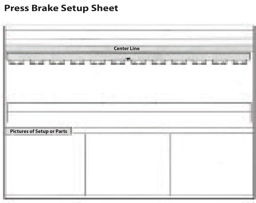
Figure 1
The reverse side (on the right) is a representation of the press brake bed, used to show tool locations. The bottom three squares are for pictures, drawings, or forming-order descriptions.
One last advantage of using setup sheets is that they describe the forming order for the part; that is, they tell operators where to begin and end a bend sequence. You could enhance this by marking the first bend on the part with “Form Up 90 Degrees” or something similar. This should prevent operators from bending parts backward.
Backgauging
The second item from your question that stood out regards backgauging. Where are your operators gauging the parts from at the press brake? Right now they are more than likely stopping off a scalloped edge, a byproduct of the punching process. The blank also may have tapered edges, which can come from the repositioning of the sheet during punching or laser cutting.
Gauging off these edges places all the error on the overall dimension of the part (see Figure 2). These manufacturing errors add up and, in all likelihood, give you no choice but to build a custom part at the end of a series to correct for those cumulative errors.
Instead, gauge in a negative position off a feature, as shown in Figure 3. Backstopping this way places all errors in the part onto the outside flanges. This holds the sides (second flange) and the overall dimension, thus removing all cumulative error from a series of panels. In some cases, you may need to design the flat blank with gauging tabs, which operators can snap off after forming.
Material Variability
The third item from your question that stood out was the thickness variation, which makes it impossible to determine the exact depth of penetration into the die opening, especially with galvanized sheet.
To account for this variation, cut strips from the skeleton that the blank came from and use them as setup pieces. These test pieces will ensure the bend angle and forming dimensions are correct before you place the actual part into the press brake. The test piece doesn’t have to match the working flange dimension of the actual part. The test piece flange can be something like an inch, just to check the backgauge calibration before you call up the part program on the control.
You didn’t mention your method for checking the finished part. Never confirm a dimension with a tape measure; it is not a precision instrument. Instead, use a combination square set or a custom-built fixture to check the overall size after the first two flanges are already in the workpiece. You can then make any final adjustments to hold dimensions before completing all the bends.
This process will ensure that all the cumulative error goes to the outside flanges and not into the side flanges or overall dimensions. It is effortless to hold ±0.010 inch using this method—without a hammer.
Punch Nose Radius
Varying bend angles can affect the second-flange gauging, the part dimensions, and, ultimately, how well things fit together in assembly. It is vital that you limit angular variations. As much as possible, try not to bend parts sharp, which creases the inside radius of the bend. This is especially important for consistency when you are working with galvanized materials. A sharp punch nose radius will amplify all the variables within the material and lead to inconsistent bend angles and dimensions.
Also note that “sharp” is a function of the material and not the tooling. I cover the subject in some detail in my Bending Basics textbook as well as several previous Bending Basics columns. Visit thefabricator.com and type “sharp bends” in the search bar, and you’ll find a few of them.
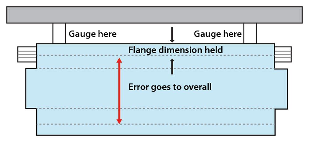
Figure 2
Standard gauging is susceptible to edge irregularities and tapers introduced during a sheet repositioning operation on the cutting machine.
Just Scratching the Surface
Change the way you gauge if you want to hold the overall dimension. Place the inherent error where it creates the fewest number of issues for the process. Finally, don’t bend parts sharp but instead choose a punch nose radius as close as possible to, but not larger than, the naturally floated inside radius of the piece.
If you implement these practices in your facility, I am confident that you will find a marked improvement in overall quality. Best of all, you should never have to build any more of those custom, one-off panels at the end of an assembled series.
Of course, when it comes to best practices, the ones described here just scratch the surface. Press brake operations have many, many more best practices that you can use to improve productivity and quality. You only need to seek them out.
Steve Benson is a member and former chair of the Precision Sheet Metal Technology Council of the Fabricators & Manufacturers Association International®. He is the president of ASMA LLC, steve@theartofpressbrake.com. The author’s latest book, Bending Basics, is now available at the FMA bookstore, www.fmanet.org/store.
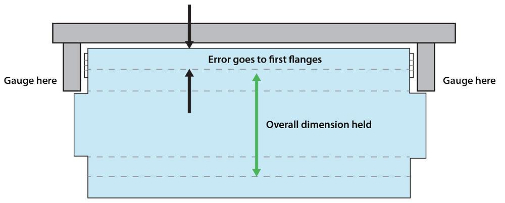
Figure 3
Gauging from a negative position helps hold the overall dimension. Errors go to the first flanges. In these situations, you may need to create gauging tabs that operators can snap off after bending.
About the Author

About the Publication
subscribe now

The Fabricator is North America's leading magazine for the metal forming and fabricating industry. The magazine delivers the news, technical articles, and case histories that enable fabricators to do their jobs more efficiently. The Fabricator has served the industry since 1970.
start your free subscription- Stay connected from anywhere

Easily access valuable industry resources now with full access to the digital edition of The Fabricator.

Easily access valuable industry resources now with full access to the digital edition of The Welder.

Easily access valuable industry resources now with full access to the digital edition of The Tube and Pipe Journal.

Easily access valuable industry resources now with full access to the digital edition of The Fabricator en Español.
- Podcasting

In this episode of The Fabricator Podcast, Caleb Chamberlain, co-founder and CEO of OSH Cut, discusses his company’s...
- Trending Articles
1
Tips for creating sheet metal tubes with perforations

2
Supporting the metal fabricating industry through FMA

3
JM Steel triples capacity for solar energy projects at Pennsylvania facility

4
Fabricating favorite childhood memories

5
Omco Solar opens second Alabama manufacturing facility
