


Contributing Writer

As a professional consultant, I find many tooling problems can be resolved just by reverting to the basics. Problems that seem insurmountable often are a direct violation of die engineering and maintenance fundamentals.
To troubleshoot a stamping die, you need to follow three basic die functions—and you need to follow them in order.
The first step in troubleshooting a die is to locate the part or blank properly in the die. You can do this using perimeter gauge pins, internal gauge pins, pilot holes, or the shape of part nested on a locating punch. Until you locate the part properly in the die, you won’t be able to secure the part or perform accurate work on it.
One common violation of this principle occurs frequently in progressive dies. Progressive dies typically use pilot pins to locate each part within the tool. The pilot pins’ effective diameter must extend beyond the surface of the pressure or stripper pad so that they can properly locate or register the part before securing it with pressure. If the pilot pins’ effective diameter is below the surface of the pressure pad, the pins will try to locate the part after it is secured. This will likely cause the pins to bend, break, or deflect or result in distorted or elongated holes in the strip. In addition, the parts will be mislocated, causing all sorts of defects.
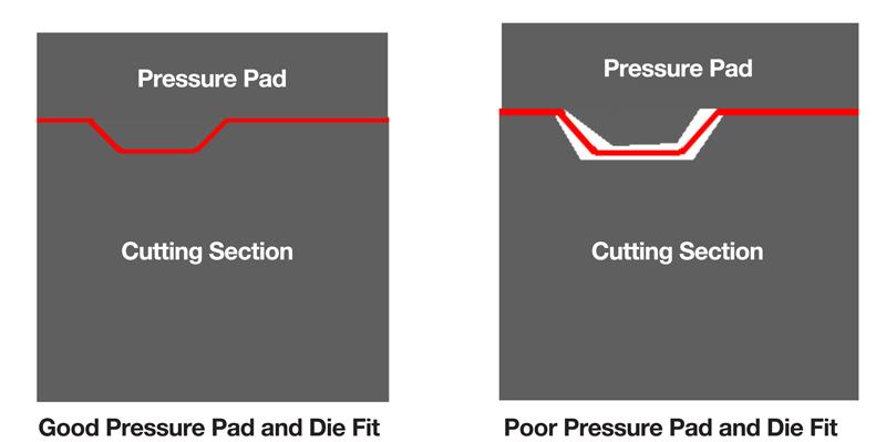
The second step in troubleshooting is to secure, hold, and support the part. No cutting or forming can take place until the part is located and secured. Pressure pads, drawing pads, and strippers are commonly used to secure parts. If you have formed the part in a previous operation, such as forming a bump in a flat blank, and now want to cut the part, the secondary die section and pressure pad must fit the contour of the part precisely.
The pressure pads and strippers must have adequate force so that they do not allow the gauged part to move during forming operations. In the case of deep drawing, the drawing or pressure pad must have adequate force to control metal flow into the drawing cavity and over the punch.
Poorly fitting, bent, or distorted pads or strippers often do not secure the parts adequately, so the parts move when being formed or cut (see Figure 1).
This results in nonconforming geometries, inconsistency, and defects such as large burrs and distorted features. Pads must be thick enough to resist deflection under load and contain enough spring pressure to secure the part properly.
The third step in troubleshooting is to perform work, such as metal cutting and forming. Don’t start any work until the part is properly located and secured.
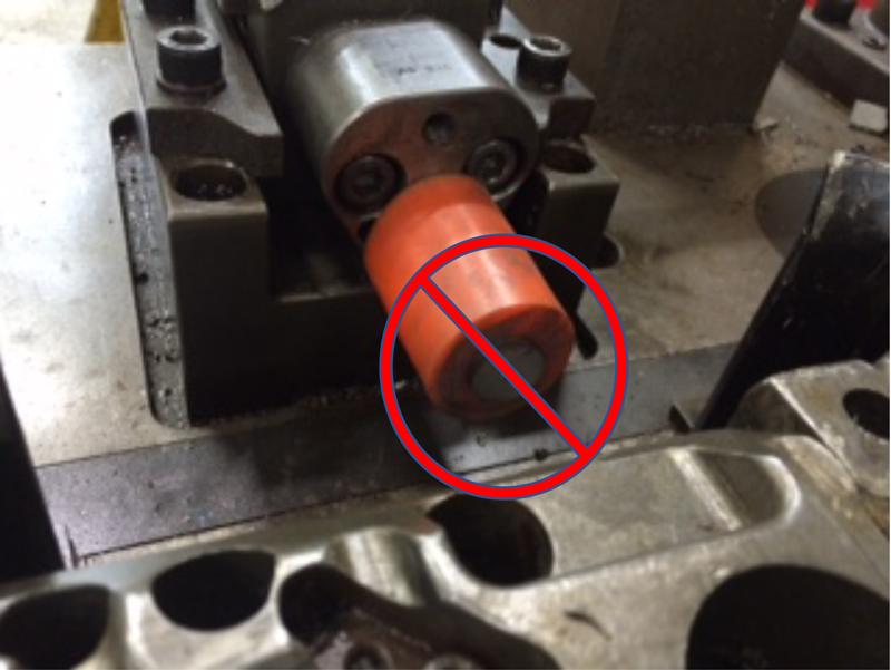
If you have a urethane stripper below the surface of a pierce punch, metal cutting is taking place before the metal is secured to the die surface, which can cause problems getting the punch out of the part, as well as distorted holes and features (see Figure 2).
And in a drawing die, if the drawing or pressure pad sits below the top surface of the forming punch, you have not secured the blank before metal forming. The loose metal can wrinkle before the pad makes contact, and wrinkling is difficult to remove, especially if it is happening on the draw pad surface. To flatten the wrinkles before more punch entry, you will need high draw pad pressure. Unless you are using a very high-tonnage hydraulic pressure system, flattening the wrinkles will be nearly impossible.


The Fabricator is North America's leading magazine for the metal forming and fabricating industry. The magazine delivers the news, technical articles, and case histories that enable fabricators to do their jobs more efficiently. The Fabricator has served the industry since 1970.
start your free subscription
Easily access valuable industry resources now with full access to the digital edition of The Fabricator.

Easily access valuable industry resources now with full access to the digital edition of The Welder.

Easily access valuable industry resources now with full access to the digital edition of The Tube and Pipe Journal.

Easily access valuable industry resources now with full access to the digital edition of The Fabricator en Español.
Seth Feldman of Iowa-based Wertzbaugher Services joins The Fabricator Podcast to offer his take as a Gen Zer...


