


Draw cushions for mechanical presses
Features and developments
 |
The draw cushion (also called the die or bed cushion) is one of the most important parts of a single-action draw press. It has considerable influence on part quality.
The main function of the cushion is to provide a flexible, controlled blank holder force, which fixes the workpiece between the upper die and blank holder. This force must be controlled precisely to guarantee optimal material flow during the forming operation.
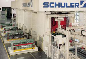
The use of a draw cushion in the lead-off press of a press line (see Figure 1) is recommended for producing consistently high-quality parts through reproducible production parameters.
The draw cushion for mechanical presses has to be more powerful than for hydraulic presses, because slide velocity is faster, and the slide impact to the cushion is harder (see Figure 2).
 |
| Figure 1 The use of a draw cushion in the lead-off press of a press line is recommended for producing consistently high-quality parts through reproducible production parameters. |
The draw cushion performs a number of functions over the entire slide stroke cycle:
- Preacceleration to adapt to the slide speed
- Pressure buildup to the required blank holding force
- Drawing operation with programmable cushion force over the length of the drawing stroke and individually for each cylinder
- Pull-down of the cushion at bottom dead center (BDC) to prevent part damage
- Upstroke into the pickup position and controlled upstroke into the start position
Preacceleration
Preacceleration of the die cushion minimizes the impact of the upper die on the blank holder. Adapting the cushion to the slide velocity improves the quality of parts and lifetime of dies and reduces noise.
Preacceleration is calculated by the cushion control for slide kinematics, crank angle, stroking rate, and draw depth parameters. Preacceleration can be selected or canceled.
Pressure Buildup
The cushion force is generated after contact of the slide and upper die with the blank holder. The elasticity of the complete system, and in particular the oil head in the lower cylinder chamber, results in a certain stroke length to build up the desired cushion pressure.
 |
| Figure 2 The requirements of the drawing operations in the lead-off press determine the type of draw cushion to be installed. |
The actual stroke for pressure buildup is determined by the pressure of the cushion and drawing stroke (height of oil head).
Drawing Process
During the actual drawing process, the blank is formed between the upper and lower die and held with a predetermined force by the blank holder. The draw cushion provides this blank holder force by displacing oil out of the hydraulic cylinder. The process is controlled by pressure via one proportional valve per cylinder (see Figure 3). This means that a pressure sensor permanently measures the oil pressure in the cylinder, compares it with the required value, and opens the proportional valve accordingly.
The blank holder force either can be kept constant or programmed in force profile. Such force profiles can be individually programmed for each cylinder module with regard to the permissible pressure difference. Finished parts can be damaged by resilience of the cushion if pads or ejectors are used in the upper die. To prevent this, the cushion will do an additional controlled downstroke at BDC.
 |
| Figure 3 The draw cushion provides blank holder force by displacing oil out of the lower cylinder area, which is controlled by pressure via one proportional valve per cylinder. |
Pickup Position and Upstroke
The drawn part is stripped off the bottom die by the upward motion of the draw cushion and brought to the pickup position. The timing and stroke of this motion to the pickup position are programmable.
After the part has been removed from the die, the draw cushion returns to top dead center (TDC) in a controlled manner without overshooting, so it is ready for the next cycle (press stroke). The timing, or crank angle, of this upstroke motion also can be programmed.
Modular Draw Cushion
The modular draw cushion system is a new development that allows stampers to tailor fully hydraulic draw cushions to their specific needs. All active control processes for the draw cushion functions (preacceleration, draw force control, relief stroke at BDC, controlled upstroke, and pickup position) take place within the cylinder modules rather than requiring separate actuators.
Because of the compact, uncomplicated design and stiffness of the hydraulic system, vibration problems are avoided. An extended force range and precise blank holder force are provided. The number of spare parts is reduced, and the cushion is easy to maintain because cylinder modules are identical.
 |
| Figure 4 Modular hydraulic cushions can be designed with one, two, four, or six points using the same modular components. |
Each cylinder module is an independently functioning unit. The necessary drawing force is achieved by combining several units. The cushion control keeps the modules synchronized with each other.
Depending on the requirements in the first drawing station, the cushion can be designed with one, two, four, or six points using the same modular components.
Maximum force per cylinder can range from 90 to 220 tons, with usable drawing strokes programmable from 2 to 13.75 inches (see Figure 4).
The ability to program the force of each cylinder, independently of each other, along the drawing path enables the operator to vary the force acting on the die over a wide range.
Andreas Lauke is manager of engineering and development with Schuler Presses, P.O. Box 929, D-73009, Goeppingen, Germany, +49 7161 66-736, fax +49 7161 66-207, andreas.lauke@spg.schulergroup.com, www.schulergroup.com.
About the Author
About the Publication

subscribe now

The Fabricator is North America's leading magazine for the metal forming and fabricating industry. The magazine delivers the news, technical articles, and case histories that enable fabricators to do their jobs more efficiently. The Fabricator has served the industry since 1970.
start your free subscription- Stay connected from anywhere

Easily access valuable industry resources now with full access to the digital edition of The Fabricator.

Easily access valuable industry resources now with full access to the digital edition of The Welder.

Easily access valuable industry resources now with full access to the digital edition of The Tube and Pipe Journal.

Easily access valuable industry resources now with full access to the digital edition of The Fabricator en Español.
- Podcasting

Seth Feldman of Iowa-based Wertzbaugher Services joins The Fabricator Podcast to offer his take as a Gen Zer...


