


Contributing Writer
For automotive sheet metal parts, the simulation of forming processes such as deep drawing and stretch forming is growing in importance, which is impacting product design, process engineering, and material selection.
Sheet metal forming simulations of automotive body parts can be categorized according to the method used, such as one-step or accurate incremental finite element simulation, and the stage of the development process at which they are implemented.
Typically, at the beginning stages in a vehicle's development cycle (for example, during concept development or in the early prototype phase), simulations can only be done with one-step methods because process engineering or tool construction has not yet been carried out. One-step methods typically provide preliminary feedback, such as a rough estimate of the location (but not the absolute value) of critical strain or wrinkling zones in the sheet.
To obtain more accurate results, incremental simulations are required. In the case of forming processes such as deep drawing or stretch forming, the simulation needs to correctly model the tools (punch, die, blankholder) and forming parameters (blank shape, blankholder forces, drawbeads, etc.). To do this, a computer-aided design (CAD) model of the tooling is required, which is usually available only during later prototype phases or when production tooling is created.
With incremental simulations, automotive product designers and process engineers can very accurately model and determine the feasibility of manufacturing parts such as side panels, fenders, frames, pillars, hoods, etc. Die geometry and manufacturing process parameters can also be optimized.
As a result, the use of simulation methods can lead to cost savings in tool construction and die tryout phases if fully integrated into the development process. Then, simulations can significantly reduce the overall development time and increase product quality.
This article discusses the integration of sheet metal forming simulations in the vehicle development process. It considers the different phases in a vehicle's development, the different simulation methods that are applicable, and the data required for each case. It also describes the results that can be achieved from the simulations.
A feature of vehicle development in recent years has been a growing insistence on speeding up the process and lowering the cost of developing vehicles that weigh less. This is done with a more extensive use of high-strength steels, aluminum, magnesium, and plastics, and the steadily increasing use of tailored blanks.
Making components out of these materials poses problems, because the forming process is more complicated than with mild steel, and fabricators have less experience with it. Therefore, simulating the forming process at the development stage is becoming more important.
Figure 1 shows the typical phases in the development of a vehicle. Today, a number of simulation techniques are available for achieving the different objectives at the respective stages.
Figure 1
During this phase, the designer of the part can take into account various forming issues. One way for the designer to do this is by practical experience. However, for new materials—high-strength steels, aluminum, and magnesium—many detailed questions have not yet been fully answered, so experience does not help determine how the parts should be made.
Expert systems contain knowledge that can be called upon at any time. However, the care and maintenance of a large database are major tasks. In addition, users must have self-discipline to surrender their knowledge to that of the expert system. Finally, questions still exist about the use of new materials.
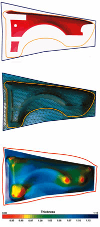
The forming simulation method chosen depends on the results to be obtained and the data available at the particular phase of development. Figure 3 shows the input data and typical results of one-step simulation methods. With these methods, usually only the component's geometry is needed for the simulation. The material characteristics and the sheet thickness are sufficient bases from which to obtain a first indication of the part's feasibility.
More accurate one-step results can be obtained by including elements in the mathematical model to allow for the important influence of the tool (blankholder, drawbeads, etc.). For example, one program automatically generates a simplified addendum and flange, which make a good basis for more exact calculations (see Figure 4). In addition, these surfaces can be used for later tool design and method plans.
Using this technique even at this early stage, the blankholder force, drawbeads, and friction under the blankholder can be calculated, always taking into account the material in question.
Currently, the outcome of a one-step simulation must be viewed as a rough assessment of feasibility. Even so, in the early stages of development, the results are precise enough to allow the design of a feasible component that the methods planner can approve.
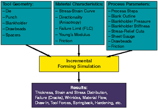
More accurate calculations for optimizing the process can be gained with the aid of incremental methods. Here, the forming process can be replicated exactly, and, starting with a blank, the deformation can be calculated as it will happen in the press.
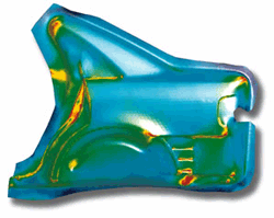
Necessary for this simulation is a CAD description of the tools (see Figure 5). This data, however, is not available until later in the vehicle's development (prototype phase, preproduction stage). The integration of incremental methods into the development process will therefore occur mainly at these later stages.
Other input data includes the material characteristics and a description of the process parameters. Incremental simulations yield all the relevant parameters that interest the forming expert, from strain distribution, sheet thickness, and cracks, for example, to springback in the trimmed part, stress distribution, and hardening. Hence, with these methods, it is possible to optimize the tool as well as the component.
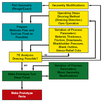
A methods plan is drawn up on the basis of the part's geometry, which may be known approximately or exactly, depending on the stage of development.
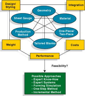
Figure 2
If no simulations are done, the tool is then machined. Only when the tool is completed can the part feasibility be verified. Any alterations require laborious reworking in the tool shop and possibly a changed methods plan or modified part geometry, which is still possible at this time.
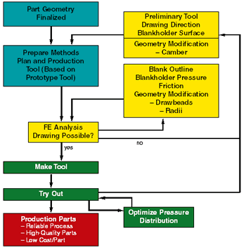
If incremental forming simulation is used when developing the prototype tool (see Figure 6), time and costs can be saved. Almost all refinements and modifications of the CAD surface data can be done before starting to make the tool. For example, one die manufacturer reduced total die tryout time from 44 to 20 weeks (more than 50 percent) using incremental simulations on a floor panel assembly of eight parts. Required changes in the methods plan can also be quickly identified.
Furthermore, precise information can be obtained on the process reliability and the likely feasibility limits by selectively varying the individual process parameters such as material characteristics and sheet thickness.
When integrating forming simulation into the making of regular production tools, the issues are different than at the prototype phase. The part's geometry is essentially final, so changes in geometry must be avoided at all costs. The main objective is therefore to ensure process reliability, which is necessary for mass production. In addition, the component must be of the required quality, such as for external automotive parts that are visible to the customer.
Much as in the prototype phase, the methods plan is prepared first, and then the tool is designed. Traditionally, the tool is then made, but not until the tryout phase can the production process be deemed reliable. Changes at this point are very costly in terms of time and money.
In the worst case, the tryout may reveal that the part cannot be made, which would mean a revision of the press setup or even alterations to the part, at great expense.
By integrating forming simulation into the development process (see Figure 7), the tool can be verified before buying the die castings, so that changes can be made at a reasonable cost. By varying the process parameters, process reliability and component quality can be optimized.
For example, one automobile manufacturer developed a draw die that could not produce parts to its specifications. This $200,000 die was going to be written off as unusable, but the manufacturer carried out incremental simulations to optimize the press parameters and was then able to produce parts with allowable tolerances.
Work at the tryout stage is then restricted to optimizing the pressure distribution in the binder, which, because of manufacturing tolerances, cannot be calculated in advance.
When tailored blanks are employed for a component, it is possible to use the right sheet material of the right thickness in the right place. Unfortunately, the location of the weld seam as determined in the design phase (for instance, to minimize weight) frequently creates problems in manufacturing. Here, forming simulation offers a way to position the seam early on to ensure reliable production.
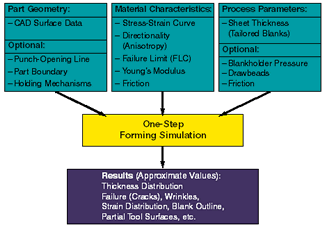
Figure 3
A new method for simulating tailored blanks has been developed. With this method, in the case of blanks made up of different sheet gauges, it is not necessary to replicate the different thicknesses in the tool.
Various thicknesses are allowed for in the contact algorithm of the simulation program, so if the seam location is altered, geometry changes in the tool are not needed. It is thus possible in a few hours to calculate various alternative positions for the seam and to optimize the weld site with regard to the forming operation.
Simulation of the deep-drawing process is an important step at every stage of a vehicle's development. Applying simulation techniques consistently in each development phase can save on the cost of tools and the time spent making them.
In particular, when using tailored blanks, forming simulation can be used to optimize the weld seam location before the tool is made. Through simulations, process reliability of the tools and quality of the components can also be improved.
Dr. Ing. Volker Steininger is General Manager with AutoForm Engineering Deutschland GmbH, U.S. phone 888-428-8636, U.S. fax 888-528-8636. He can also be contacted through U.S. distributor EASI Engineering, 2025 Concept Drive, Warren, Michigan 48091. AutoForm Engineering develops and markets specialized FEA simulation software for sheet metal forming (one-step and incremental), which is used primarily by automobile manufacturers and automotive suppliers. Lead-in photograph courtesy of Audi AG, Ingolstadt, Germany. Original article presented at The International Body Engineering Council (IBEC) '97 conference, September 30 to October 2, Stuttgart, Germany. Copyright Society of Automotive Engineers, Inc.

The Fabricator is North America's leading magazine for the metal forming and fabricating industry. The magazine delivers the news, technical articles, and case histories that enable fabricators to do their jobs more efficiently. The Fabricator has served the industry since 1970.
start your free subscription
Easily access valuable industry resources now with full access to the digital edition of The Fabricator.

Easily access valuable industry resources now with full access to the digital edition of The Welder.

Easily access valuable industry resources now with full access to the digital edition of The Tube and Pipe Journal.

Easily access valuable industry resources now with full access to the digital edition of The Fabricator en Español.
In this episode of The Fabricator Podcast, Caleb Chamberlain, co-founder and CEO of OSH Cut, discusses his company’s...


