


Minimum inside sheet metal bend radius vs what's recommended
For typical applications, the minimum radius isn’t recommended
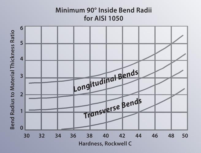
Figure 1
Longitudinal bending, or bending with the material
grain, increases the required minimum inside radius of
the bend.
Q: In a previous Bending Basics article, you mention a “material’s tensile reduction percentage” used for calculating the minimum inside bend radius of various metals. You described a rough rule to find a steel’s minimum bend radius: Divide 50 by the material’s reduction percentage, as specified by the material supplier, subtract by 1, and then multiply by the plate thickness.
To state your example, “If the steel has a tensile reduction value of 10 percent, divide 50 by that value: 50/10 = 5. Next, subtract 1 from that answer: 5 – 1 = 4. Now, multiply that answer by the plate thickness. If the material is 0.5 inch thick: 4 × 0.5 = 2. So in this case, the minimum inside bend radius is 2 times the material thickness.”
If I am looking at properties for A36 steel, I see elongation properties between 18 and 21 percent. Is this the property to which you refer? Using the median of 20 percent and material thickness of 0.5 in., would this equate to [(50/20) – 1] × 0.5 = 0.75. Then I’d multiply this answer by the material thickness: 0.75 × 0.5 = 0.375 in. However, a bend allowance chart I have from our press brake manufacturer gives different information. For 0.5-in.-thick plate, it shows an inside bend radius of either 0.781 in. for a 5-in. die width, or 0.625 in. for a 4-in. die width.I know you mentioned that the calculation you gave is a rough guide, but the discrepancy between the formula and the brake manufacturer’s bend allowance chart seems significant; it’s off by a factor of 2. Is the 20 percent number correct, or did I apply the equation incorrectly?Minimum Bend Radius vs Recommended Bend Radius
A:You have the formula correct at 0.375 in. However, I believe you misinterpreted the meaning and how it relates to your bend allowance chart. The calculated 0.375-in. radius is the minimum producible inside radius for this material and not the recommended inside radius that you see on the bend allowance chart.
It’s true that the harder and thicker the plate is, the greater the minimum bend radius. The minimum inside bend radius is even larger when bending with the grain. In steel between 0.5 and 0.8 in. thick, grade 350 and 400 may have a minimum bend radius of 2.5 times the material thickness when transverse bending, while longitudinal bending may require a minimum bend radius that’s 3.75 times the material thickness (see Figure 1).
Also note that all these are just examples; actual minimum radius values vary by grade. For steel, aluminum, and stainless, you will find a variety of minimum bend radii-to-thickness ratios, and you will need to research these values in data provided by your material supplier.
But again, all this refers to the minimum inside bend radius—what’s physically possible if you have press brakes and tooling that can handle the high tonnage. The recommended inside bend radius is what’s optimal in a typical application.
The radii from the bend allowance chart (see Figure 2) is based on 15 percent of the die opening and represent basically a one-to-one relationship between the material thickness and the inside radius when using the recommended die opening of 5 in. By using the 5-in. die and thereby producing that one-to-one inside radius-to-material-thickness ratio, you will achieve the best results in your product and the most stable bend angles.
Assuming you have the tonnage and could force the material into a die opening only 2.5 in. wide—just five times the material thickness—you would achieve the minimum inside radius that’s possible in an air form. However, for many reasons I wouldn’t recommend you do this. Nonetheless, some folks do this if they have high-tonnage machines.
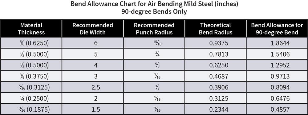
Figure 2
This portion of a bend allowance chart gives the recommended inside radius, not the minimum inside radius that can
be produced. Also note that this is not a bend deduction chart. The bend allowance is used to figure the bend deductions
you need for the flat layout. Editor’s Note: This chart is for illustrative purposes only and should not replace bend
allowance charts provided by the press brake manufacturer.
The 5-in. die is 10 times the material thickness, and, as a general rule at these thicknesses, 10 to 12 times the material thickness is correct and common. I, along with your press brake manufacturer, would not recommend using a smaller die opening, if for no other reason than to avoid damage to your press brake and tooling. If your die opening is less than 8 times the material thickness for sheet metal, or less than 10 to 12 times the material thickness for plate, you will see a dramatic increase in the amount of pressure required to bend the material.
Calculating Metal Bend Radius Tonage
Also, lifting the workpiece during forming can increase the tonnage required dramatically. Figure 3 shows 10-gauge (0.135-in.) material; that’s technically sheet metal and a long way from 0.5-in. plate, but the principle is the same. The material will need to be lifted during forming over a 1.125-in. die opening.
To calculate the additional tonnage, you need the weight of steel per square foot for the given thickness, which you can get from your supplier or on gauge charts for common materials. The weight of 10-ga. carbon steel per square foot is 5.625 pounds, so for 10-ft.-wide material that extends out in front of the press by roughly 10 ft., the total weight of the sheet in front of the press is:
Material length (ft.) × Material width (ft.) × Weight of steel per square foot (lbs.) =
Total weight (lbs.)
10 × 10 × 5.625 = 562.50 lbs.
Next, multiply the total weight by 60 (one-half of the sheet width in inches) and divide that by half the die opening width. Finally, divide the bending force by 2,000 lbs. (1 U.S. ton), and you get the total additional tonnage required for lifting the part.
Total weight (lbs.) × Half of sheet width (in.) /
Half of die opening width (in.) =
Bending force (lbs.)
(562.5 × 60) / 0.5625 = 60,000 lbs.
of bending force
60,000 / 2,000 = 30 U.S. tons
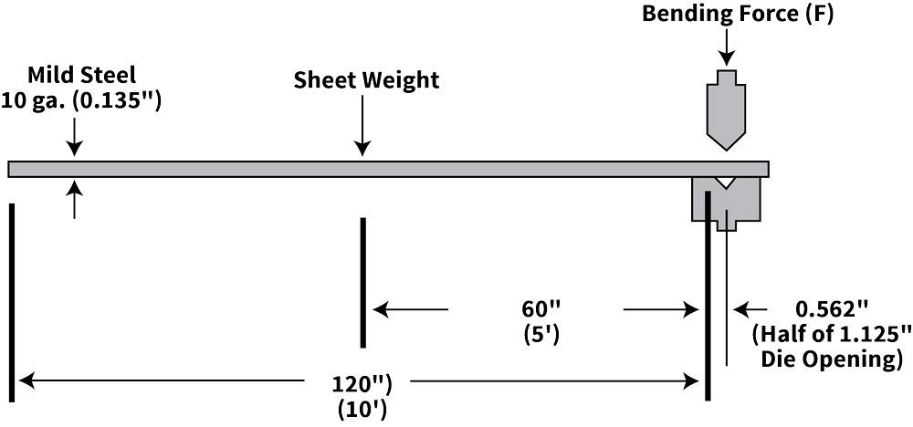
Figure 3
Lifting the workpiece during forming can increase the tonnage required.
Next, use this formula to calculate forming tonnage for mild steel (all variables are in inches unless otherwise noted):
[(575 × Material thickness2)/Die opening] × Bend length in feet = Forming tonnage
[575 × 0.1352/1.125] × 10 = 93.15 tons to bend
Finally, add the tonnage required to lift the part:
93.15 + 30 = 123.15 tons
to bend and lift this part
You can reduce the tonnage by using a larger die opening, but this will require you to take into account a larger inside bend radius and, therefore, a larger bend deduction and bend allowance for the flat-blank calculations. For instance, a die opening of 1.25 in. will require 88.84 tons to form and 27.00 tons to lift, for a total of 115.84 tons. A die opening of 1.50 in. will require 69.86 tons to form and 22.50 tons to lift, for a total of 92.36 tons.
And this is just for 10-ga. material. Going back to the original question, you can see what would happen if you tried to form 0.5-in.-thick material in a die opening that’s only five times the material thickness.
About the Author

About the Publication
subscribe now

The Fabricator is North America's leading magazine for the metal forming and fabricating industry. The magazine delivers the news, technical articles, and case histories that enable fabricators to do their jobs more efficiently. The Fabricator has served the industry since 1970.
start your free subscription- Stay connected from anywhere

Easily access valuable industry resources now with full access to the digital edition of The Fabricator.

Easily access valuable industry resources now with full access to the digital edition of The Welder.

Easily access valuable industry resources now with full access to the digital edition of The Tube and Pipe Journal.

Easily access valuable industry resources now with full access to the digital edition of The Fabricator en Español.
- Podcasting

Seth Feldman of Iowa-based Wertzbaugher Services joins The Fabricator Podcast to offer his take as a Gen Zer...


