


Senior Editor

Imagine you know nothing about sheet metal and it’s your first day in the press brake department. Where do you begin? Well, the basics. Getty Images
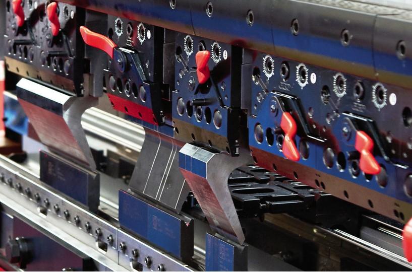
It’s your first day on the job, and you’re training to one day become a press brake operator. You see some tools on a cart next to every press brake. On some machines you see operators using a single set of tools, while on others you see people set up multiple sets of tools across the machine.
The operation might seem simple enough. An operator takes a piece of sheet metal or plate and slides it between two tools. You see the top tool (the punch) descend toward the lower tool (die) to bend the part. No big deal, right?
Wrong. In fact, the number of things happening makes bending one of the most complicated and least understood processes in metal fabrication. And it all starts with how the machine’s punch and die interact with the sheet metal.
For years The FABRICATOR editors have listened to business leaders in metal fabrication opine about the lack of experienced talent, so they hire greenhorns, people who never worked in sheet metal, perhaps never in manufacturing in any capacity. Some say they need to teach their most entry-level employees how to read a tape measure.
Many in this business start from scratch, which means companies serve not only as employers but also teachers—and along with welding, sheet metal bending at the press brake remains one of the most difficult processes to teach.
A brake department might have two kinds of newbies: One is the person who might just want to run a press brake, clock out, and go home. That’s fine, but what follows probably isn’t for him. Another kind, the curious newbie, might have that spark of interest that one day could help him or her to progress up the ladder to press brake lead or supervisor, or at least an informal leader and technical guru.
Even so, what follows starts with the extreme basics, like defining what a “bend radius” really is. From there it gives a brief taste of some fundamental concepts. You won’t find formulas or even specific best practices. For those, the rookie can turn to our monthly Bending Basics column by The FABRICATOR’s own bending guru, Steve Benson, as well as his book by the same name, published by the Fabricators & Manufacturers Association. If you’re an experienced bending guru, this article isn’t at all for you, but it could be for the new hire you might be training.
Some engineers in this business tell stories about receiving a solid CAD model of a sheet metal part from a customer, seeing a bend, and finding there’s no radius at all. Modern software has made this less common, but it’s a testament to how unfamiliar sheet metal bending is even to those in manufacturing. So here are the most basic of basics.
Every bend has an angle and radius. The bend angle is intuitive, though when you look at part drawings and measure formed pieces, you’ll need to know whether the angle specified is internal or external to the bend (see Figure 1).
But what about the radius? Metal fabrication uses the term radius to describe curves in sheet metal, plate, and the tools used to create them. Think back to middle school and high school geometry: Draw a circle, place a dot in the center, and from that dot draw a straight line to the edge. The distance of that straight line is the radius. The smaller the radius (the shorter that line), the smaller the circle gets, and the sharper the circle’s curve becomes.
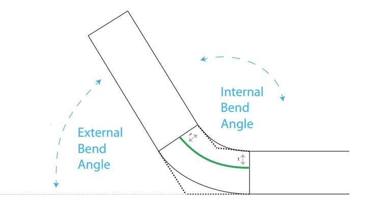
FIGURE 1 A specified bend angle can be either internal (between the two legs of the bend) or external (outside of the bend).
On some drawings you might see a bend with a specified radius; if you see, say, R .120 with an arrow pointing to the inside of a bend, that means the bend should have an inside bend radius (that is, the radius along the inside surface of the bend) of 0.120 in. The radius is not the distance between where the bend starts and ends (there’s another term for that). Instead, imagine drawing a circle with an edge that overlaps the bend’s curve (see Figure 2). That circle (and, hence, that bend) should have an inside bend radius of 0.120 in.
When a press brake bends, the metal elongates ever so slightly. This has to do with the nature of compression and expansion on the sheet or plate as it’s bent. Consider the cross section of the sheet metal thickness in Figure 3. Near the outside of the bend you get expansion, near the inside you get compression, and the interaction of these forces pulls the neutral axis—the boundary between compression and expansion—toward the inside bend radius. Press brake pros define that shift as the k-factor, and it’s that shift that causes metal to elongate, or to grow.
Pros (and modern software) use the k-factor and other variables to account for that elongation. It involves calculating the bend allowance (length of the bend’s neutral axis) and the bend deduction—that is, the amount you deduct from the original dimensions to account for that elongation, so that when the piece is bent, its dimensions “grow” to the desired size.
If you’re a total greenhorn, this probably goes a bit too much into the weeds. But knowing, at least in a general sense, what happens to metal when it bends gives you a good starting point to learn more.
When you see an operator pick up a laser-cut or punched piece of sheet metal (sometimes called a blank), he slides it between the punch and die against the backgauge fingers, or stops, which keep the blank in the right place for bending. If the workpiece isn’t steady against the stops or if something is wrong with the backgauge fingers’ position, bending is sure to go awry.
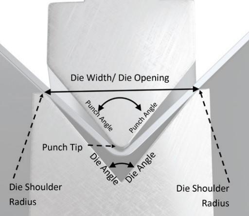
The shape of those tools—the upper punch and the lower die—governs in part how bending takes place. Conventional punches have a punch tip radius (the smaller the radius, the sharper the punch) and a punch angle. The lower V die has a die opening (also called V opening or die width). The angle of that V is the die angle, and the transition into that V opening is called the die shoulder radius (see Figure 4).
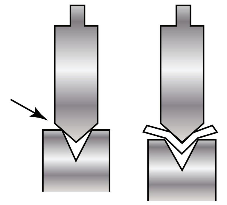
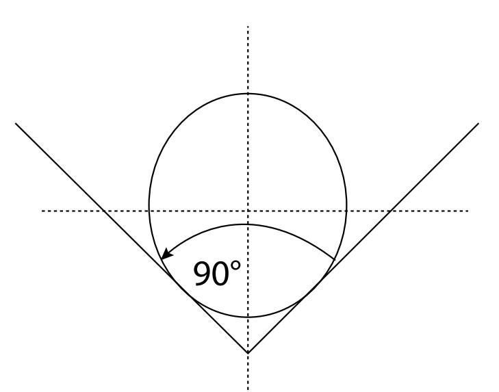
The punch angle shouldn’t be larger than the die angle. Figure 5 shows why. If a punch with a larger angle descends into a V die with a smaller angle, you can damage your tools and possibly create a dangerous situation.Look around the shop and you’ll see punches of various shapes, and for most of them you can probably discern where the angle is. It’s the angle of the metal leading to the punch tip, where the punch touches the metal. But if your shop bends large workpieces to large radii, you also might see round punches; instead of a tiny punch tip, you have a large round bar at the end of the punch body. So what’s its punch angle? Unless it’s customized in some way, large round punches effectively have a punch angle of 90 degrees (see Figure 6).
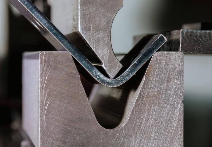
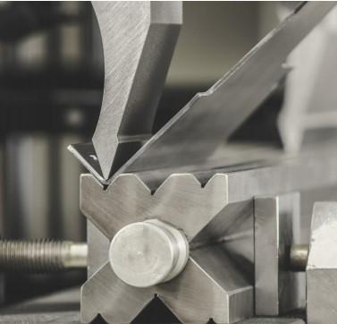
The operator initiates the bend, and how the blank interacts with the punch and die depends on the bending method used. The very beginning of the bend cycle is the same regardless of the bending method: The punch nose pushes the sheet into the die opening, sliding it over the die shoulder radii on either side of the V.
From here, though, the bending action depends on what bending method is being used. If you work at a general fabricator on an old press brake, you might be bottoming (see Figure 7). The punch nose presses the sheet metal until it “bottoms” at the bottom of the die, stamping the punch nose radius into the bend and forcing the sheet metal against the die angle. In bottoming, the punch tip radius determines the inside bend radius, and the die angle determines your bend angle.
Of course, most shops these days perform air bending, sometimes called air forming (see Figure 8). With this method, the die opening, not the punch tip radius, determines the inside bend radius. Specifically, the bend radius forms as a percentage of the die opening. In air bending, the wider your die opening, the larger radius you’ll achieve. Sure, the punch tip can affect air forming, especially if it’s too small or large for the job at hand, but it typically doesn’t play a leading role in determining the bend radius.
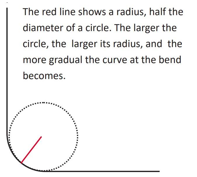
FIGURE 2 Here’s a trip back to basic geometry. The bend radius is not the length along the bend surface, but the radius of the bend’s curve, as shown.
Wider dies also reduce the bending force you need to create the bend (that is, the forming tonnage). Thicker materials take more force to bend and, hence, usually require larger press brakes using larger die openings. Choose a die opening that’s too narrow for the job, and you risk damaging your machine, tooling, and yourself.
Also in air bending, the punch and die angle have no direct effect on the bend angle. Instead, the bend angle is determined by how far the punch tip descends into the die opening, sometimes called the depth of penetration.
The die opening also governs your minimum flange length—that is, the narrowest bend you can make with the tooling you have (see Figure 7). Basically, you need to have the work sit in a stable manner on the die shoulders. Otherwise, the piece will fall into the die space as soon as the punch starts pushing downward.
In air bending, choosing a narrower die angle allows you to increase the depth of penetration to account for springback, which is the tendency of the sheet metal to spring open slightly after the punch releases bending pressure. A narrower die angle also allows you to bend a narrower flange—that is, you can have a lower minimum flange requirement—though again, narrowing the die opening can increase forming tonnage significantly.
You’ll probably hear the pros around you say they choose die openings that are some multiple of the material thickness. There are alternative ways to choose the best die for the job, and the calculations vary with the material thickness, strength, and numerous other factors. But the bottom line is this: When people choose a die, they want to choose one that can help them form the workpiece best while also keeping forming tonnage safely below the limits of what the machines and tools can handle.
Back to your first day on the job, you see operators pulling punches and dies from carts. What kind of tools are they? Well, that depends on the kind of bending you’re doing, and a telltale sign can be how operators are measuring their parts. If all you see are tape measures, chances are pretty good that the brake isn’t bending precision work. If a bend angle is within a quarter inch, the part’s just fine, and customers probably aren’t fussy about the inside bend radius either.
In these operations, you might see some planed tooling, named after how it’s made, with a planer. These tools come in long segments that can be used as is or cut to shorter lengths. If they are cut, they need to be labeled so that if a job requires longer tools, they can be reassembled in the exact order and orientation they were cut. If you don’t mate the pieces correctly, the tools can cause significant accuracy issues (see Figure 9).
If you see digital calipers and radius gauges, chances are the brake is bending precision work, which usually requires precision-ground tools, almost always segmented into short lengths. These tools are made to extraordinarily tight tolerances.
The industry’s tools are classified in several general categories, including American tools, European-style tools, New Standard tools, and others. One difference between them is how the tools mount to the press brake, as well as how bending force flows through them. The various tool types have their pros and cons. As a newbie, you need not dive into the weeds, but it’s good to know which type your shop uses, how they mount properly to the machine, and what the effects of reversing the tools would be (see Figure 10).
Why would you need to reverse a tool? That depends on the bend sequence, or the sequence of bends you need to form the entire workpiece. Simple brackets might have one or two; complex workpieces might have half a dozen or more.
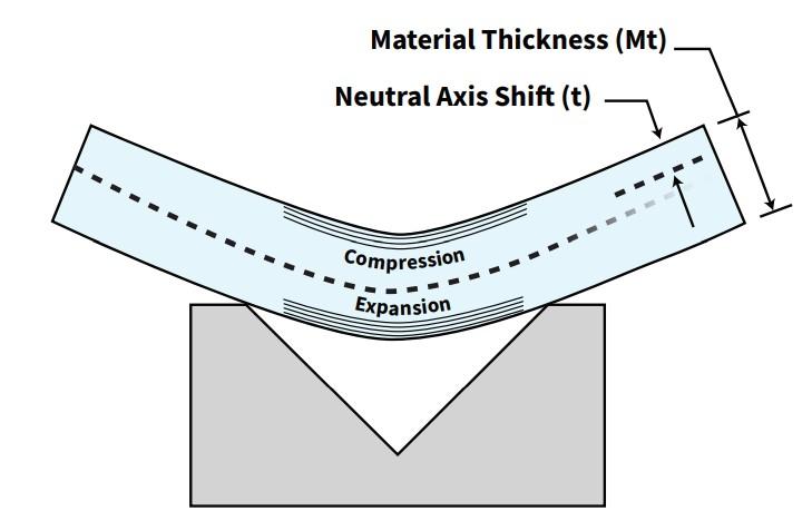
FIGURE 3 The k-factor describes the material’s neutral-axis shift during bending.
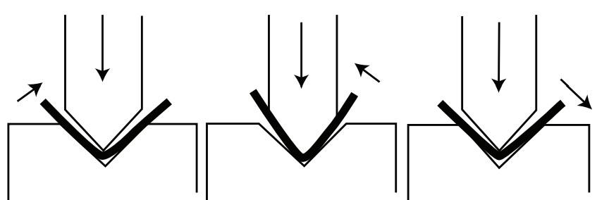
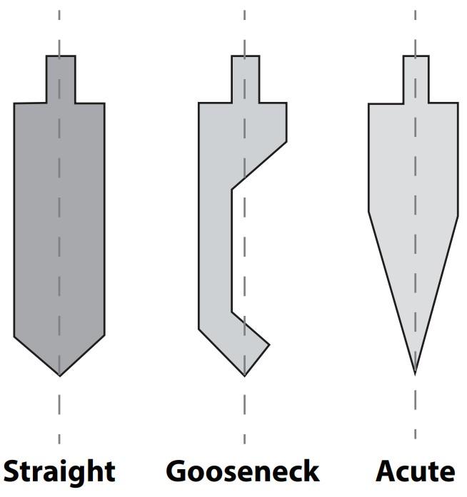
When performing so many bends, you need to use a sequence that prevents you from colliding with previously bent portions of the workpiece. Punch types abound, and Figure 11 shows three of them. The right punch can help you avoid collisions with previously formed portions of the workpiece.
For instance, the right gooseneck can help avoid a collision with a previously formed flange. Rotate that gooseneck so it’s facing the other way, and you have a setup that can avoid colliding with previously formed parts. For certain parts, you might even have window punches, or punches with windows cut out of the tool body to allow clearance for previously formed flanges.
Parts with multiple bends might require dies with different V openings, too. Double-V dies give you two different die openings on one tool, while four-way dies (which look like an X when viewed from the side) give you four different die widths—or as Figure 12 shows, sometimes more. If you need a different die opening, you flip to the side you need.
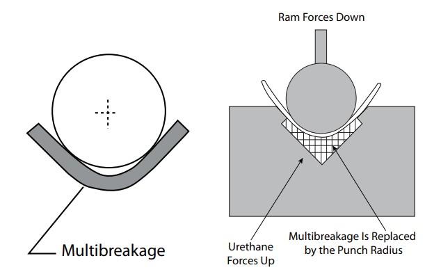
You also might see a plethora of nonstandard tools that form specific shapes in the metal. You can even have tools with urethane components that can protect the workpiece from marring and sometimes aid the forming process. Consider that round punch again. When bending plate, it tends to pull away from the punch, a phenomenon known as multibreakage. A urethane pad at the bottom of the die can counteract this. The application in Figure 13 shows a urethane pad placed in what’s called a relieved die, where the die angle is cut away to allow the punch to descend deeper, to overcome springback and form the desired angle.
Look around the shop and you might see some machines with just a single punch and die, while others might have multiple tools positioned across the press brake bed. If operators set these up the right way, they can perform stage bending—that is, carry a part through multiple bends on one machine.
The setups look simple, but they aren’t. For one thing, all the tools in that setup need to share the same shut height, or the space between the ram (just above the tools) and bed (below the tools) at the bottom of the stroke. Setup personnel might use tools designed with common shut heights, or they might use shims and risers to raise each die to meet its corresponding punch (see Figure 14).
Such setups have become more commonplace thanks to modern software that programs backgauge movement and simulates complicated bend sequences. In the old days, operators had to manually turn a hand crank to move a backgauge finger to the right position. And those positions were limited, which in turn limited the ways operators could slide the workpiece against the backgauge before initiating each bend. Now the machine moves the backgauge to the needed position. Some parts still need creative gauging solutions, but suffice it to say, backgauge fingers are much more capable than they used to be.
If you’re a newbie, or if you’ve worked in fabrication but you just now started in the press brake department, you’re entering the sheet-metal-bending fray at an exciting time. Your department might have a smattering of older machines alongside a collection of shiny new ones, machines that give you 3D simulations of the bend sequence, tell you exactly where to place tools, and even place the tools for you.
That said, all that impressive equipment doesn’t change the physics of bending. If newbies learn what really happens when metal bends—part of the basic grammar of metal fabrication—they can build a solid foundation for a long, fulfilling career.
Editor's note: The information for this article came in part from Bending Basics by Steve Benson.


The Fabricator is North America's leading magazine for the metal forming and fabricating industry. The magazine delivers the news, technical articles, and case histories that enable fabricators to do their jobs more efficiently. The Fabricator has served the industry since 1970.
start your free subscription
Easily access valuable industry resources now with full access to the digital edition of The Fabricator.

Easily access valuable industry resources now with full access to the digital edition of The Welder.

Easily access valuable industry resources now with full access to the digital edition of The Tube and Pipe Journal.

Easily access valuable industry resources now with full access to the digital edition of The Fabricator en Español.
In this episode of The Fabricator Podcast, Caleb Chamberlain, co-founder and CEO of OSH Cut, discusses his company’s...


