Contributing Writer
- FMA
- The Fabricator
- FABTECH
- Canadian Metalworking
Categories
- Additive Manufacturing
- Aluminum Welding
- Arc Welding
- Assembly and Joining
- Automation and Robotics
- Bending and Forming
- Consumables
- Cutting and Weld Prep
- Electric Vehicles
- En Español
- Finishing
- Hydroforming
- Laser Cutting
- Laser Welding
- Machining
- Manufacturing Software
- Materials Handling
- Metals/Materials
- Oxyfuel Cutting
- Plasma Cutting
- Power Tools
- Punching and Other Holemaking
- Roll Forming
- Safety
- Sawing
- Shearing
- Shop Management
- Testing and Measuring
- Tube and Pipe Fabrication
- Tube and Pipe Production
- Waterjet Cutting
Industry Directory
Webcasts
Podcasts
FAB 40
Advertise
Subscribe
Account Login
Search
An overview of important tools for illustrating and documenting a product’s design
Exploded Views and Display States make it happen for CAD engineers
- By Gerald Davis
- Updated January 8, 2021
- January 15, 2021
- Article
- Manufacturing Software
Editor's Note: If you would like to download the 3D CAD files associated with this column, click here.
Development of “the product” has moved from the design stage to the documentation stage. Fabrication of the tray, shown in Figure 1A, requires a combination of rivets and spot welds. The CAD task at hand is to prepare the 3D model for use in creating illustrations.
The handled box, along with this removable tray, is part of a larger (imagined) project—the FMA Tote Box. The FMA Tote Box project was introduced in August and as a “cut-length BOM project” in September.
Figure 1B shows the bill of materials (BOM) table for the entire tote box. The red rectangle and yellow highlight point out the tray’s role in the project. The drawing that is to be created for the tray will have a similar BOM table and Exploded View that shows the parts that make up the tray.
With the mainstream 3D CAD software being demonstrated, the Exploded View is part of the 3D model. 2D drawings employ such Exploded Views as a means of posing the model.
Figure 2A shows the steps—seven of them—that went into exploding all the components in the tray: two end plates, two dividers, one handle, and six rivets are the result.
Here’s a CAD tip: Rename the Exploded View as it is created to hint at its purpose. This Exploded View is useful for understanding what is needed, not necessarily how it goes together.
Illustration of the rivets and handle has a dedicated Exploded View. Figure 2B shows the three Exploded Steps used to separate the handle and rivets from the spot-welded frame. (As a side note, such Exploded Views are useful in the production of animations as well as in static images and 2D illustrations.)
For comparison and contrast in the setting of a 2D drawing, Figure 3 presents two Exploded Views and one BOM table. The big difference between these two views is in how the components are positioned in the view. Typically, the left-hand view in Figure 3, titled HANDLE RIVETS, would be used to prepare a how-to-rivet illustration.
This CAD software uses the BOM table to assign item numbers, five of them in this example. Both of the Exploded Views in Figure 3 use the same item numbers because they are linked to the same BOM table. It is possible for a drawing file to have several BOM tables. The CAD jockey controls the numbering in drawing views by linking the view to a specific BOM table.
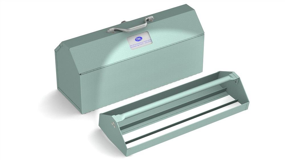
Figure 1A. The lift-out tray is a component of the tote box design. The immediate task is to document it for fabrication.
Start Exploding at the End
As a CAD work flow suggestion for creating step-by-step illustrations, start with a fully Exploded View and copy it to make the preceding illustration in the assembly sequence.
Figure 4A is showing the Exploded Views (note top-left green box) and the Display States (note bottom-left cyan box) that were created to show a sequence of welding steps. The Exploded Views position the parts, and the Display States hide or show the parts.
Figure 4B shows the setup for a step-by-step illustration:
- PARTS REQUIRED FOR WELDING is at the top left.
- STEP 1 and STEP 2 correspond to the dividers.
- STEP 3 and STEP 4 address the end plates.
Each of the five views is set to select a unique Exploded View and Display State from the assembly.
This is good progress, yet much remains for the tote box project; for example, we’ll cover individual part drawings and welding and riveting drawings for the lids and frame in upcoming installments. Will we include flat layouts on our drawings?
About the Author
subscribe now

The Fabricator is North America's leading magazine for the metal forming and fabricating industry. The magazine delivers the news, technical articles, and case histories that enable fabricators to do their jobs more efficiently. The Fabricator has served the industry since 1970.
start your free subscription- Stay connected from anywhere

Easily access valuable industry resources now with full access to the digital edition of The Fabricator.

Easily access valuable industry resources now with full access to the digital edition of The Welder.

Easily access valuable industry resources now with full access to the digital edition of The Tube and Pipe Journal.
- Podcasting
- Podcast:
- The Fabricator Podcast
- Published:
- 05/07/2024
- Running Time:
- 67:38
Patrick Brunken, VP of Addison Machine Engineering, joins The Fabricator Podcast to talk about the tube and pipe...
- Trending Articles
White House considers China tariff increases on materials

A deep dive into a bleeding-edge automation strategy in metal fabrication

Majestic Steel Arkansas fully operational

A visit to Automate 2024 reveals the future might be now

Rivian to expand Illinois facility to manufacture midsized SUV

- Industry Events
Laser Welding Certificate Course
- May 7 - August 6, 2024
- Farmington Hills, IL
World-Class Roll Forming Workshop
- June 5 - 6, 2024
- Louisville, KY
Advanced Laser Application Workshop
- June 25 - 27, 2024
- Novi, MI
Precision Press Brake Certificate Course
- July 31 - August 1, 2024
- Elgin,

