


Contributing Writer
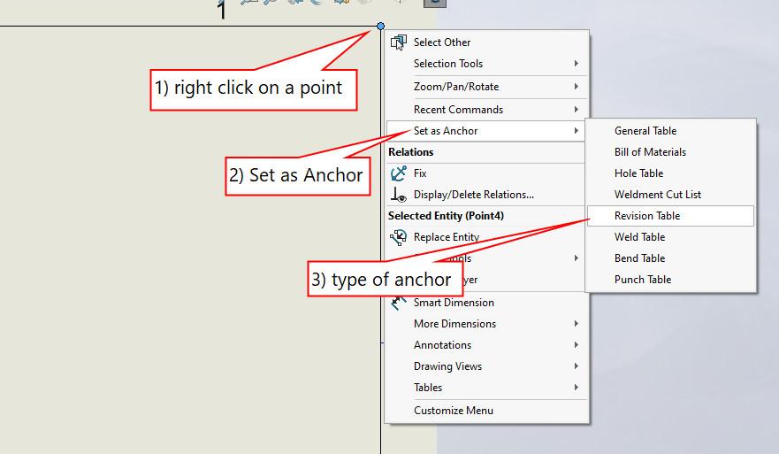
FIGURE 1A. Here’s how to position an anchor point for a revision table when editing a sheet format: Right-click on a point, select Set as Anchor, and select Revision Table as the type of anchor.
Terms in italics indicate terminology in the brand of mainstream 3D CAD being used for this presentation. The design of a drawing’s sheet format includes decisions regarding the anchor points that control the locations for various tables that may appear on the drawing. As an example scenario, a goal for the revision table could be to always have it appear in the upper right corner of drawings.
An anchor point in the sheet format controls the default position of a table. It prevents the table from accidentally being moved by the mouse. An anchor point also serves as a snap point during the drag-and-drop of tables onto a drawing.
In terms of CAD operation, the design of drawing templates and drawings for production share a fortunate overlap—the same CAD skills are needed to create each. In terms of what detail is to be included, templates are sparse compared to a production drawing.
For example, a revision table template will just have headings in the template, no rows. In contrast, a revision table in a production drawing is likely to have one or more rows of information.
Save early, save often, and test the progress: As the design of the template progresses, a table may be saved as a table template with a right-click, then save as template. That table template then can be inserted into other drawings or templates. The same can be done for a sheet format.
To add an anchor point for a table to the sheet format’s design:
Anchor points can’t be deleted. They are merely relocated or ignored. Unless someone pays attention to locating anchor points, the various types are likely to default to the same (probably not very useful) location.
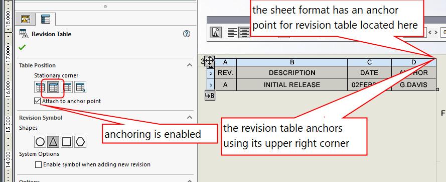
Having an anchor point properly located in the sheet format is only half the battle. The table itself must know how to attach to the anchor point in the sheet format.
Figure 1B shows the revision table’s property manager on the left and the table itself on the right. To set up a table for use with an anchor point:
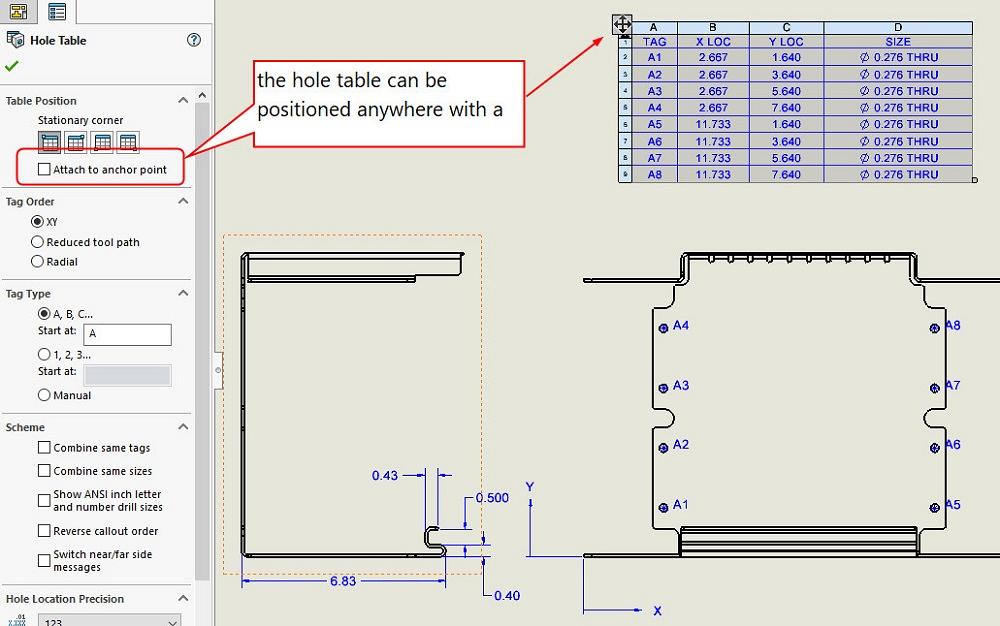
Here’s a CAD tip: If there is a table that won’t move because it is anchored, uncheck the box to alter the table’s anchoring behavior. Using Figure 1D as an example, this hole table might not need an anchor point, so we’ll disable its anchoring and drag it to a good location.
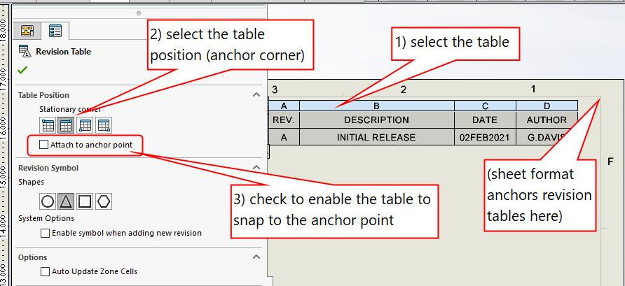
FIGURE 1B. Here’s how to set table position preferences to work with anchor points in a sheet format: Select the table, select the corner to use, and check the box.
Here’s a side note: The property manager for the table offers several options, depending upon the type of table. All tables have settings for their anchor point. The use of the zone column in the revision table (to hint at where to look for changes on the drawing) was discussed in the July 2022 episode of this column.
The setup of anchoring for any table follows the same process: Set the anchor point in the sheet format and set the table positioning properties for the table.
The victory is performance.


The Fabricator is North America's leading magazine for the metal forming and fabricating industry. The magazine delivers the news, technical articles, and case histories that enable fabricators to do their jobs more efficiently. The Fabricator has served the industry since 1970.
start your free subscription
Easily access valuable industry resources now with full access to the digital edition of The Fabricator.

Easily access valuable industry resources now with full access to the digital edition of The Welder.

Easily access valuable industry resources now with full access to the digital edition of The Tube and Pipe Journal.

Easily access valuable industry resources now with full access to the digital edition of The Fabricator en Español.
In this episode of The Fabricator Podcast, Caleb Chamberlain, co-founder and CEO of OSH Cut, discusses his company’s...


