


Contributing Writer
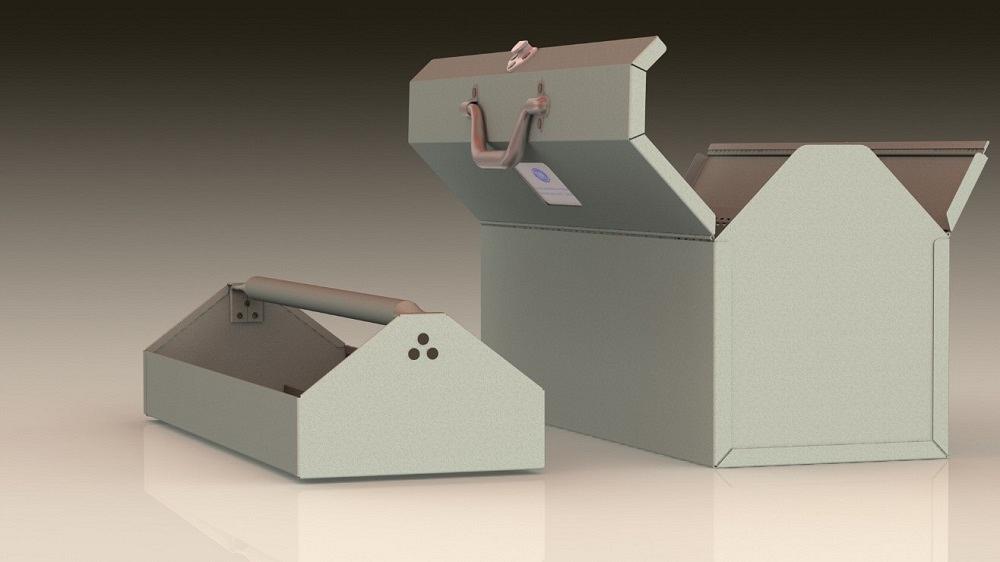
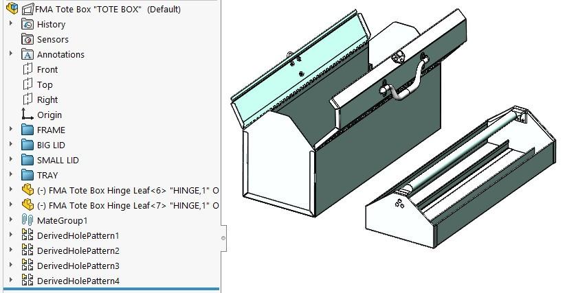
Figure 1: A tote box with lift-out tray features a bifolding latched lid and a replaceable identity label.
Editor's Note: If you would like to download the 3D CAD files associated with this column, click here.
The tote box shown in Figure 1 has been the topic of discussion in previous episodes of this column, as an “apprentice project” in August (“CAD props prove useful in training, verifying, illustrating,”) and as a “cut-length BOM project” in September (“Avoiding mistakes while providing data for a BOM table,”).
In this episode we imagine that a review meeting has held forth that a tote box design has been approved. The approved features include the lift-out tray, the bifold hinged lids, the bale latch, the folding handle, and the plastic window for the identity card.
With the shape, size, and features finalized, the next stage in CAD effort is to produce drawings for fabrication. In this stage of the work, the methods of manufacture are to be finalized and presented along with the completed drawings for the next stage of review.
As we plan to prepare the drawings, we note the physical arrangement of components in this project. The tray is easy to lift and separate from the hinged box. The hinged lids are captive, not easily removed but easy to unlatch and swing open.
The tray requires welding for the walls and divider as well as a riveting for the handle. Likewise, the large hinged lid is both welded and riveted. Same with the small hinged lid.
The piano hinges are to be cut to length, deburred, and then separated by nondestructively knocking the pin loose from the leaves. All three parts are to be handled as a matched set while welding one leaf to a lid and the other leaf to the corresponding side of the box. When the welding is completed, the pin is reinstalled to complete the hinge installation.
Figure 2 shows the current state of the bill of materials (BOM) table for the project. The component’s product manufacturing information (PMI), such as material, thickness, and source, is displayed in the BOM table. Note that the cut length and width columns are legacy items from the previous episode. It is shop-specific for a BOM table to include this kind of data, but it is good to know that dimensional information—almost any information in the model, for that matter—can be linked for BOM table display.
In Figure 2, all components are at the same level. There are no subassemblies modeled in this project so far. That could be OK. Something like Figure 2 could be the first sheet of a multisheet drawing, showing all the details of the tote box. As with assembly instructions for a plastic model car, such a single-file documentation method would be handy when one person is making one of these on their own schedule.
In this scenario, we do not know when the various parts will be manufactured or assembled. Four kinds of fabrication documents are required: drawings for individual piece parts, drawings for weldments, drawings for riveting, and drawings for final assembly/operation. Unlike a step-by-step multisheet drawing, these fabrication drawings may not all travel together. They will get distributed wherever as needed.
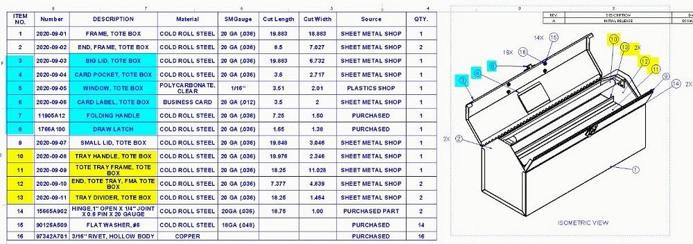
Figure 2: The BOM for the tote box is flat—all components at the same level. There are no subassemblies. This is not realistic and makes it difficult to produce good drawings. The yellow items should all be organized into a single subassembly. Likewise, the parts for the big hinged lid—the cyan items—should be in a subassembly.
As preparation for satisfying the documentation goals, the assembly must be restructured. Subassemblies need to be created to show items that are welded together. Also, subassemblies need to show rivets attaching hardware to weldments. This (improved) hierarchy of components in the model also results in a more realistic virtual prototype.
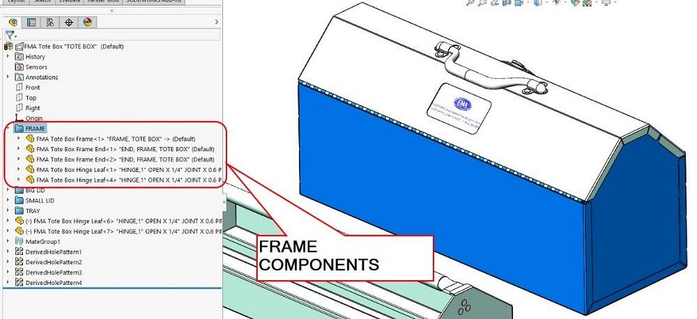
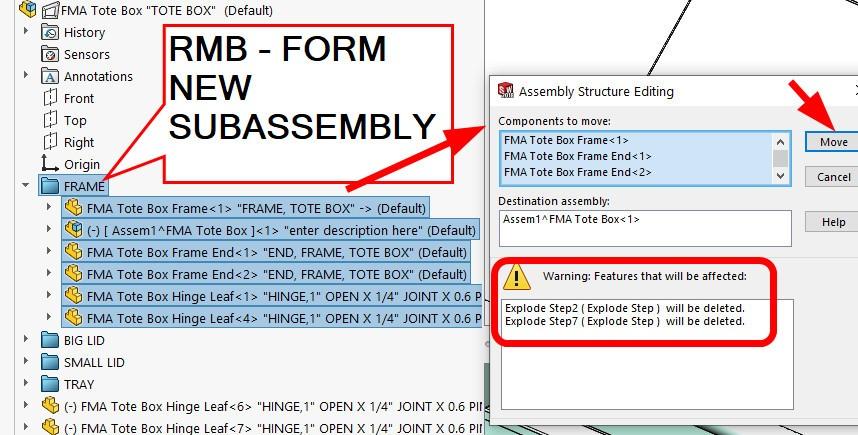
During the initial modeling, by habit the author organized the components into folders in the Feature Manager—see Figure 3A. Such folders help with locating items by reducing clutter. In Figure 3B the folder named FRAME has been selected. That folder selection in turn selects all components in the folder. Because of the author’s effort, these are all the parts specific to the frame.
A right mouse button on the folder name brings up a context menu that includes Form New Subassembly. If that is clicked, the popup dialog appears for Assembly Structure Editing, as shown in Figure 3C. Notice the warning that is boxed in red. The warning reminds us that changing the hierarchy of the assembly messes up the explode steps. We appreciate the reminder and continue by clicking on the Move-It-and-Mess-Up-Prior-Work button. (That is intended as wry CAD humor.)
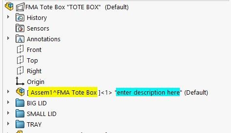
Figure 4A shows some additional consequences of forming a subassembly. We have file names to change and PMI to edit. The yellow highlighted assembly name is a wrong default file name “ASSEM1.” The cyan highlights the temporary description pulled in from the assembly template. Double-click to edit the file name. Then either select or open the file and update the PMI to correct the description.
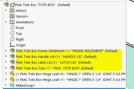
Figure 4B shows the (ta-da!) result of moving all folders (as referenced in Figure 3A) into respective subassemblies, giving them good file names, and then editing their descriptions and other PMI. A similar procedure was used to create subassemblies of the weldments and nested subassemblies of those weldments and their riveted parts.
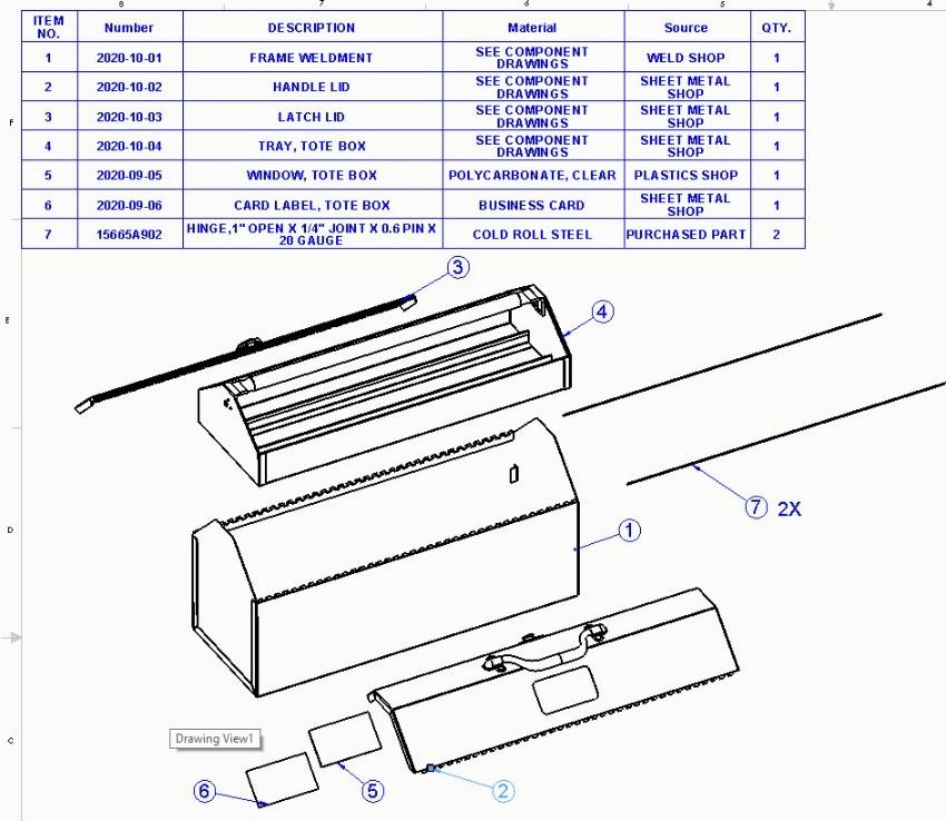
Figure 4C shows the tote box BOM after reorganizing its component hierarchy into subassemblies. The hinge pins (7) are used to attach the lids (2) and (3) to the box (1). The identity card (6) and window (5) go into place in the lid (2) as a finishing touch.


The Fabricator is North America's leading magazine for the metal forming and fabricating industry. The magazine delivers the news, technical articles, and case histories that enable fabricators to do their jobs more efficiently. The Fabricator has served the industry since 1970.
start your free subscription
Easily access valuable industry resources now with full access to the digital edition of The Fabricator.

Easily access valuable industry resources now with full access to the digital edition of The Welder.

Easily access valuable industry resources now with full access to the digital edition of The Tube and Pipe Journal.

Easily access valuable industry resources now with full access to the digital edition of The Fabricator en Español.
In this episode of The Fabricator Podcast, Caleb Chamberlain, co-founder and CEO of OSH Cut, discusses his company’s...


