


Contributing Writer
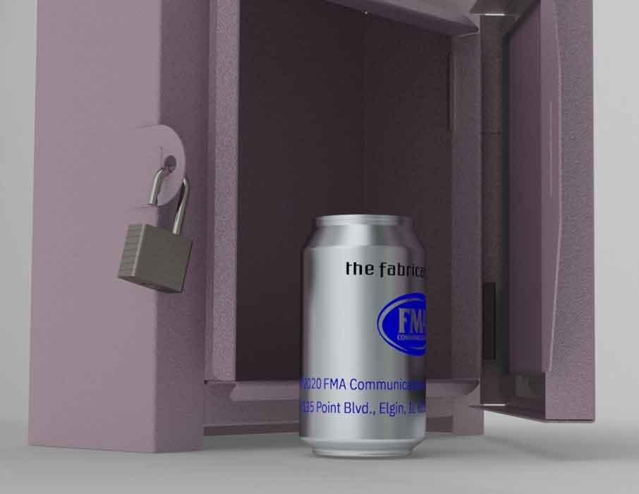
Figure 2b
Shown is a scene rendered with Visualize, a tool that offers excellent textures and shadows. Depth of field and lighting are very easy to adjust. The software makes best use of available video and CPU resources.
The internet of things (IoT) brings the blessings of browser-based CAD. With such browser-based apps, software updates and released versions are not part of the user experience. Workstation hardware is not of paramount concern. Backups are integral to use. Access to the data is versatile for collaboration. IoT CAD is clearly a useful resource for design work. A gaming-level video system is probably good enough.
For those less enthused about IoT, web-aware technology is an option. With roots deep in the Windows® OS, desktop-licensed 3D CAD still prospers, mostly because of speed of visualization, which is tied to efficient data access. Love of voluntary network connection possibly is bolstered by operational capability, because IoT is not always going to be an option.
Maybe the arcane access to a desktop PC translates as IP (intellectual property) security. While I might still cling to floppy disks and backup tapes, I’m also told that my good old motherboard still allows for hardware ugrades to video cards that are engineered for state-of-the-art 3D CAD display.
Disclaimer: This discussion of hardware and software is intended as informational rather than promotional material. We are not trying to endorse or recommend the CAD technology being demonstrated.
The FMA can shown in Figure 1a has been used as a prop in previous episodes of this column. A wireframe display of visible and hidden edges for this pop-top container puts a significant demand on the display system.
Spare me this one moment for CAD nostalgia. Black and white isometric views were considered state of the art when the author first blinked at 2D CAD. I still have a dialup modem and a boxed set of Windows 98 around somewhere. Spinning a wireframe in 3D space is still a pretty good way to evaluate the hardware capability of a workstation.
The evolution of 3D CAD display technology has resulted in a legacy of menu options in the CAD editor. The invention of shading options in the user interface was performance-driven. Today the various display modes allow for a comfortable CAD editing experience and are useful in presentation and refinement of the design.
From its beginning, the mainstream 3D CAD at the heart of this conversation embraced OpenGL graphics display technology for the CAD editor. Figure 1b shows the FMA can with OpenGL® shading in addition to wireframe edge display. The wireframe display of visible edges actually takes more time to generate than just the shaded rendering. Without the wireframe, the OpenGL 3D shaded mode is the speediest method of display and is the default.
If the 3D CAD editor is running with a limited-capacity video display driver, the software can emulate OpenGL video display commands that the hardware lacks. It is a relatively slow emulation, but it works on almost any Windows OS.
Software-emulated OpenGL can be useful when debugging a CAD installation. For example, if the system does not crash while running the OpenGL emulator, but does crash when the video card’s driver is used, then don’t use that video card/driver combination for this brand of 3D CAD.
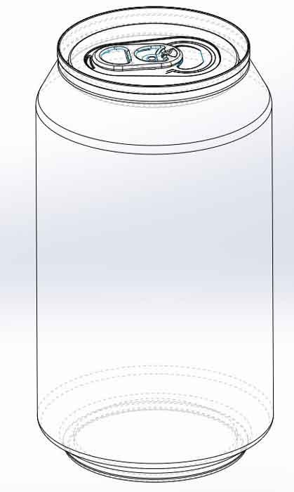
Figure 1a
Wireframe display mode has been an option in CAD from the beginning. It is often useful when selecting hidden features while editing.
To avoid the performance hit of emulated OpenGL, an OpenGL-compatible video card dramatically improves the performance of the CAD display.
RealView® graphics technology featuring better reflections, textures, and shadows in the CAD editor is a visual improvement over OpenGL. Figure 1c shows the pop-top can with decals visible and perspective mode turned on. Some workstations lag when these settings are enabled. Modern laptops and PCs should have no trouble with performance in RealView mode. Similarly, options for decals, perspective, or camera view should introduce very little lag in performance.
Back in the day when video cards were slower, RealView, OpenGL, and related view settings were offered as necessary menu options. Use the relatively speedy, but limited, OpenGL for routine modeling and switch to the heavier RealView mode only for presentations and visualization. Heavy is a description of mouse-drag response. Light-speedy is better than heavy-blurry.
Modern video systems are speedy enough to support full-time CAD editing in RealView mode. However, the almost game-like shadows and brilliance of RealView can be a mixed blessing. The ability to select a preferred display mode for the design in progress makes for a tailored work environment.
As shown in Figure 1d, Cartoon mode, like OpenGL or RealView, is a distinctive style of visualization. This mode does not strive for photorealism but instead emphasizes shape and style, resembling graphic art drawn in the commercial advertising industry. Cartoon mode in the CAD editor strongly resembles a shaded display mode available in Composer® (a tool for production of manuals, animations, and still shots), but that’s a topic for another column.
Although RealView is a prettier display mode than OpenGL, it falls short of photorealism in order to maintain lightweight performance. For photorealism, something other than RealView technology is needed.
One alternative to RealView is PhotoView 360™, an add-in to the CAD editor. If the workstation’s video system is fast enough, it is practical to run the CAD editor while in PhotoView 360 Preview mode. A final rendering of the pop-top can is shown in Figure 1e.
PhotoView 360 Preview mode is a compromise between performance and full rendering. This is handy while the model is positioned in 3D space and the scene is being refined. PhotoView Final mode ties up the hardware more than Preview mode does.
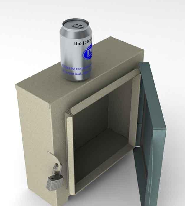
The final rendering will use every core in the workstation to calculate the ray tracings between the environment and the model. The scene shown in Figure 2a took less than a minute to render on an Intel i9 laptop with a high-end video card. PhotoView 360 is useful for creating a lovely image while keeping CAD editor near at hand.
Visualize® is similar to PhotoView360. Both produce beautifully rendered images, and both are offered with a license. The CAD editor is not compatible with Visualize, but the CAD models are. Visualize blurs the distinction between preview and final rendering; if the workstation is fast enough, then one could final-render all of the time.
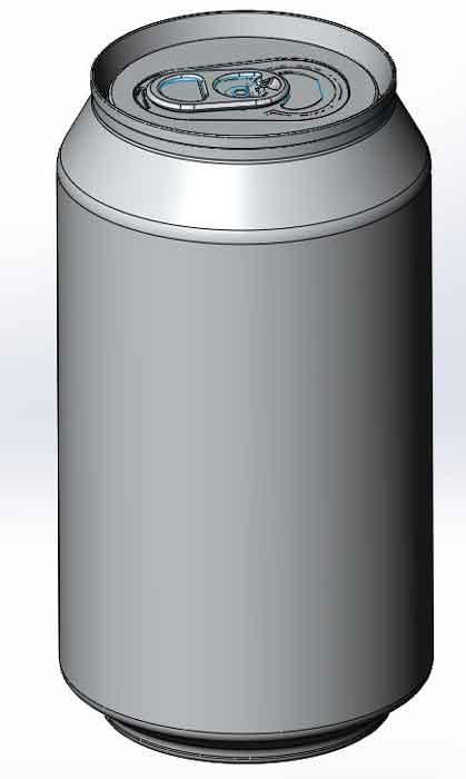
Figure 1b
OpenGL technology is the default for shading the surfaces of the 3D model. This image shows both wireframe and shaded surfaces. Calculation of wireframe display of visible edges can make the model feel heavy.
Visualize runs as a separate app from the CAD editor. The scene in Figure 2b used all default settings to move from the CAD editor to the rendering tool, basically a few mouse clicks. Once the scene was set up, it rendered the final image file very quickly.
Visualize is a powerful rendering studio. It works with any brand of CAD. The library of available environments and textures is extensive; setting up a scene with the model is an intuitive drag-and-drop process.
The user interface for Visualize evolved independently from the CAD editor. For those with experience rendering with Bunkspeed, aspects of Visualize will feel very familiar. Visualize requires a specific work flow. Accordingly, a new CAD jockey has a short but relatively painless learning curve.
I’ve found less need for PhotoView 360 since getting familiar with Visualize. However, they both have their charm.
Gerald would love for you to send him your comments and questions. You are not alone, and the problems you face often are shared by others. Share the grief, and perhaps we will all share in the joy of finding answers. Please send your questions and comments to dand@thefabricator.com.


The Fabricator is North America's leading magazine for the metal forming and fabricating industry. The magazine delivers the news, technical articles, and case histories that enable fabricators to do their jobs more efficiently. The Fabricator has served the industry since 1970.
start your free subscription
Easily access valuable industry resources now with full access to the digital edition of The Fabricator.

Easily access valuable industry resources now with full access to the digital edition of The Welder.

Easily access valuable industry resources now with full access to the digital edition of The Tube and Pipe Journal.

Easily access valuable industry resources now with full access to the digital edition of The Fabricator en Español.
Seth Feldman of Iowa-based Wertzbaugher Services joins The Fabricator Podcast to offer his take as a Gen Zer...


