


Vice President Segments, Extraction and Filtration Division
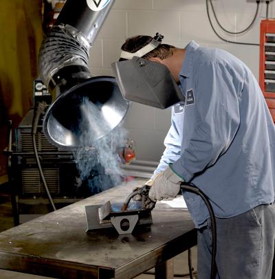
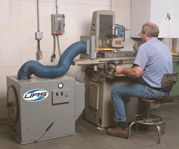
Figure 1: The hood design plays an important role in how emissions are removed from a work area, such as this welding table.
Effectively controlling harmful process emissions is an important issue facing fabricators as governmental and environmental regulations become increasingly stringent. Left uncontrolled, these emissions present health hazards to factory workers and result in reduced productivity. In addition, emissions can accumulate on floors, shelves, ledges, equipment, inventory, finished goods, and other places throughout a facility, negatively affecting product quality, machine reliability, and overall worker safety.
By using a properly designed air pollution control system including the hood, fabricators can avoid these hazards. Four key aspects of a properly designed air pollution control system are capturing the contaminant, transferring the contaminant, selecting the proper collection equipment, and selecting the proper air-moving device (fan). If any one of these elements is not properly designed, the system will not perform at an optimal level.
When evaluating air pollution control systems for their manufacturing process, fabricators typically pay more attention to the equipment specifications or ducting, often overlooking the hood. However, the capture hood (see Figure 1) is where the air pollution control system first engages the process generating the emissions. The hood’s role is as important in the overall system as the roles the other three elements play (see Figure 2).
The hood design has a direct impact on the airflow and pressure requirements for the total system. An optimally designed hood can result in less obtrusive ductwork, a smaller dust collection equipment footprint, and lower-horsepower fans. This results in overall lower system installation costs as well as lower system operating expenses because of reductions in maintenance and energy usage.
A best practice to approach hood design for new processes or to evaluate whether existing hoods are serving their purpose effectively is to first understand the hood requirements.
Hood design seeks to balance several characteristics to achieve optimal system performance. These characteristics include:
Because each of these characteristics affects the other, a fabricating company should begin hood design with a thorough review of the process generating the emissions, the contaminant itself, and operator or process interaction to help determine the hood performance requirements. The particle size, process momentum or energy possessed by the contaminant at time of capture, and any potential contaminant hazards also need to be identified and factored into the design.
For example, heat generated during welding processes causes the surrounding air and process fumes to rise rapidly. This motion or energy needs to be considered and accounted for in the hood design. In addition to process considerations, external sources of air motion that can upset hood performance—such as machinery motion, process material motion, movement of operating personnel, and natural room air currents—should be considered in the design as well.
However, pulling too much air can be detrimental to hood design and performance. Using welding as the example again, too much air can disrupt the shielding gas, potentially lowering the weld quality. On CNC machining center applications, pulling too much air results in more particulate capture than is necessary, which decreases filter life or shortens maintenance cycles. Additional flow also can lead to increased energy usage through higher pressure loss at the hood.
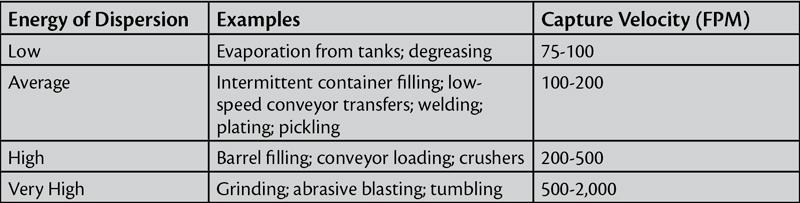
Once the design parameters are collected and the application is understood, fabricators can use this information to identify the proper capture velocity necessary to effectively capture the contaminant with a hood. Figure 3 outlines the American Conference of Governmental Industrial Hygienists (ACGIH) recommended capture velocities for typical applications. Identifying the required capture velocity is the first step in defining a successful hood design, but it must be combined with the proper type of hood to achieve the desired performance.
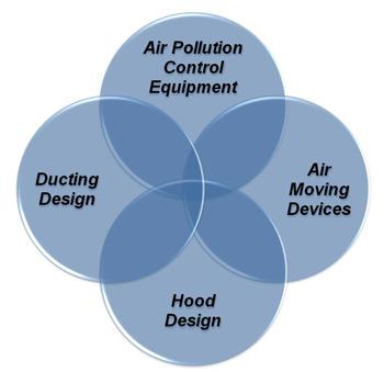
Figure 2: Air pollution control equipment, air-moving devices, ducting design, and hood design are the four keys to designing an effective emissions removal system. Often hood design is the key factor that is overlooked.
Capturing the contaminant at or near the source, referred to as local ventilation, is always recommended where practical because it requires the least amount of energy and does not allow the contaminant to migrate throughout the rest of the factory or into the workers’ breathing zone. Different applications require different hood styles or approaches to make local ventilation practical. Therefore, matching the proper hood type with the application process is also essential for achieving the desired performance.
Although hoods are available in many sizes and shapes, the three basic categories are exterior capture hoods, enclosures, and receiving hoods.
Exterior Capture Hoods. Exterior hoods capture air contaminants that are being generated from a point outside of the hood. Examples of these types of hoods are extraction arms, slotted hoods, and simple open-ended ducts. These hoods are effective if the contaminant is released with low momentum and within the hood’s effective reach. Typical applications for exterior capture hoods are processes such as thermally generated fumes and bag dumping or filling stations.
An advantage of exterior hoods is that they generally use less airflow when compared to other, larger hoods and, therefore, use less energy. They also are relatively simple to design and inexpensive to fabricate and install. The low airflow can result in reduced duct and equipment sizes. A disadvantage of exterior capture hoods is that significantly more airflow is required the farther away the hood is from the emission source. This means that, in most cases, exterior hoods need to be relatively close to the emission source to be effective and efficient.
Best practices for using external hoods include using a perimeter flange as well as a gradual taper from the hood to the duct. Incorporating these features will focus the hood capture velocity toward the extraction source and reduce the pressure loss at the hood. Figure 4 shows the developed airflow patterns of several hood geometries and the impact of these features.
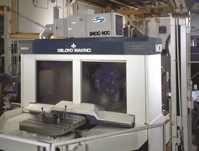
Enclosure Hoods. Enclosure hoods surround or contain the emission source with one side of the enclosure left completely or partially open. These hoods are most often applied when local ventilation is impractical because of interference, size of parts, or where emission generation rates are very high. Enclosure hoods are commonly used in applications such as abrasive blasting, spray booths, CNC machining (see Figure 5), conveyor loading, enclosed bucket elevators, crushers for mining, and vibrating screens.
The primary advantage of an enclosure hood is that it locally contains the emissions, preventing migration and protecting the workers. With its small opening to draw an inrush of air through, a relatively large space can be controlled efficiently. Disadvantages of an enclosure hood are that it is not always practical or cost-effective to enclose the entire process. If workers need direct access to parts and need to be inside the enclosure while the process is producing emissions, additional personal protective equipment is required.
An enclosure hood design is based on the ingress velocity of all open areas within the hood. Sufficient capture velocity must be achieved across these openings to ensure that the contaminant will not escape the enclosure. However, finding the proper balance is essential, because pulling too much air is not only detrimental from a pressure drop standpoint, but also can increase the loading on the collection equipment, which in turn shortens the filter life.
Receiving Hoods. Receiving hoods are designed to take advantage of the momentum or the force of the contaminant to capture it within the hood. Common examples are the hood on the discharge side of a grinding wheel that leverages the inertial forces to carry the air contaminants into the hood (see Figure 6). Another example is an overhead canopy on thermally generated fumes that uses the thermal rise to capture the contaminant.
Advantages of receiving hoods are that they typically capture the fume at or near the source and leverage the process parameters to collect the material. As a result, low flow rates can regularly be achieved with this approach. A disadvantage is that these hoods rely on a consistent process and ambient conditions to operate correctly.
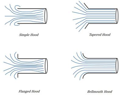
Figure 4: The airflow patterns of selected exterior hood types are shown.
Using the process information collected, including the recommended capture velocity and the hood type that best matches the process and performance requirements, fabricators can specify the hood geometry they need. Resources such as ACGIH’sIndustrial Ventilation manual provide recommendations and the equations necessary to complete the design for many types of hoods and specific processes. Although these recommendations may not precisely match the application, a general approach or strategy can be taken and applied using the specific performance requirements.
After the hood design is completed, the process of designing the ductwork and selecting the proper dust collection equipment and fan can begin.

The Fabricator is North America's leading magazine for the metal forming and fabricating industry. The magazine delivers the news, technical articles, and case histories that enable fabricators to do their jobs more efficiently. The Fabricator has served the industry since 1970.
start your free subscription
Easily access valuable industry resources now with full access to the digital edition of The Fabricator.

Easily access valuable industry resources now with full access to the digital edition of The Welder.

Easily access valuable industry resources now with full access to the digital edition of The Tube and Pipe Journal.

Easily access valuable industry resources now with full access to the digital edition of The Fabricator en Español.
In this episode of The Fabricator Podcast, Caleb Chamberlain, co-founder and CEO of OSH Cut, discusses his company’s...


