


Contributing Writer
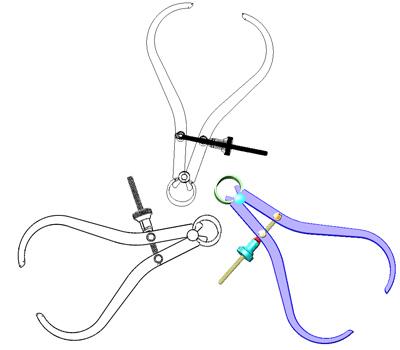
Figure 1
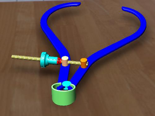
This OpenGL rendering of a caliper is shown in three ways: (clockwise from bottom right) shaded, hidden lines removed, and wireframe. This can be a very speedy design project—extra-speedy if the graphics card can handle all of the OpenGL commands.
A caliper similar to those represented in Figure 1 might be used to check the diameter on wood turnings. Three copies of the caliper are shown in Figure 1, each with shading options that are common in CAD software: shaded, wireframe, and hidden lines removed. While these shadings can be completed almost instantly on the computer, they are clearly artificial. They are handy for identifying component boundaries and very useful when operating the CAD software. In some cases, these kinds of images are good for product presentation as well.
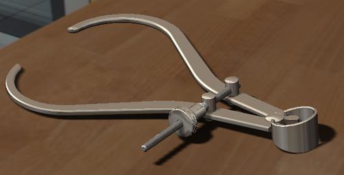
We can use the 3-D CAD software to show the same caliper model in different scenes for nearly realistic presentations. Figure 2a is an example with knurling and threads that strongly resemble the real thing.
The same caliper model appears on the bed of the lathe in Figure 2b. It is resting with rust just to the right of the cross slide under the tailstock. Lastly, Figure 2c demonstrates the caliper model appearing with a kit of lathe accessories. Any image can be used as part of the scene for a rendering.
Depending on the target audience, the 3-D CAD software may provide the finished image or perhaps provide a preliminary image for additional editing with other software. The 3-D CAD software used for preparing the illustrations accompanying this article can be licensed with the rendering tools to make very impressive images.
Regardless of the software brand, a CAD jockey changes his workflow when moving from 3-D modeling to a session of photo shooting. When the CAD jockey puts on a photographer’s cape, a transformation occurs in the menus. We’re not going to step through those menus. Our goal is to outline a rendering workflow that minimizes false starts: Make a good 3-D model, look at it through a camera, position a scene around the model, adjust the lighting, and render the image.
As a side note, professionals in the product shot business were at it long before 3-D CAD was invented. They have their terminology, such as model, f-stop, and backdrop. A photographer’s model is indeed 3-D, but not in a CAD sort of way. Image professionals probably use software that is dedicated to digital image processing. Adobe®, for example, offers a suite of tools for photo editing. MODO®, 3ds Max®, and many other brands have spectacular tools for creating a synthesized yet realistic world.
In many cases, it is wise to have the CAD jockey hand a 3-D model for import into software operated by a professional in the image-making trade. Other situations allow the CAD jockey to explore all of the tools at hand. If you’re just starting out, you will find many online training resources. (I highly recommend books on SolidWorks® PhotoView 360™ from the software developer for those working in that 3-D modeling environment.)
Using 3-D CAD as a realistic-product-shot maker requires skill in manipulating the model, using a camera, and selecting the scene. Each of those three elements contributes significantly to the realism of the final image.
1. Model Matters. The surfaces of the model reflect light. The appearances applied to those surfaces change how the light is reflected. Because the model will be manipulated in ways specific to the image and not necessarily in ways beneficial to manufacturing, we recommend using a copy of the production model for the product shot. For example, you might find that chrome looks more “realistic” than silver and want to change the material just for looks, not for specification.
2. Camera Matters. In the real world, a camera is pointed at a target. The camera lens bends the light rays coming from the scene on their way to the flat surface of the film. The photographer selects the lens to control how much of the real scene is warped to fit into the relatively small and flat area of film in the camera. A wide-angle lens catches more light, but distorts the image to look fish-eyed. A narrow-angle lens is telescopic—less distortion but also less sense of depth in the image.
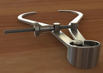
Figure 2a
The PhotoView 360 rendering, a function of the SolidWorks software, uses appearances on the model surfaces to reflect light rays coming from the spherical environment. This results in reflections on the model surface, shadows under the model, and reflections of the model on the background floor.
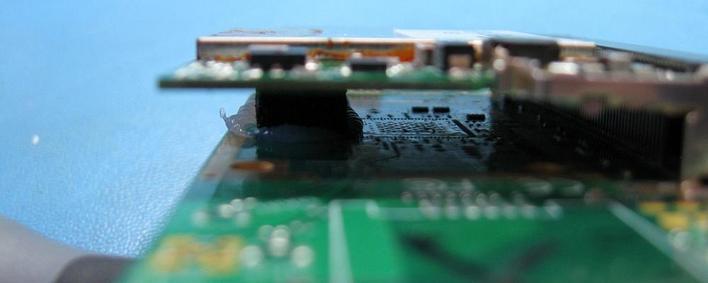
The photographer also focuses the lens on a target some fixed distance in front of the camera. Objects that are closer to the camera will be out of focus. The same is true for those farther away from the ideal focus point. Depending on the lens, the loss of focus may be hard to see or it may be dramatic. The range of this acceptably sharp focus is referred to as the “depth of field.” The circuit board pins under the daughter card are in focus in Figure 3, while most of the rest of the image is blurry.
Here is one more emphasis on reality before we delve into software: The photographer looks through a viewport in the camera to get a preview of what will be captured on film. In many cameras this is accomplished by a beam splitter so there is no difference between viewport and film. Imagine viewing the world only through that camera’s viewport, swinging your head around with a camera locked to your forehead; it would be doable, but not practical.
Such is the life of the CAD jockey: The scene can be seen only through a camera.
3-D CAD is wonderful when it comes to spinning a model around to visualize what the real item would be like if it were floating in space. That may seem to be the case, but the software is actually holding the model stationary and is spinning the viewport around the model to let you see it from wherever.
The software’s viewport is functionally the same as the photographer’s camera. For the CAD jockey, the viewport, which also could be called the graphics window or display area, is the camera. Early on in their careers, CAD jockeys learn how to change the camera’s lens. They often think they are toggling perspective mode on or off, but all that’s happening is a switch from a wider angle to something like a telescopic lens angle.
You might spend a significant amount of time using 3-D CAD software without ever thinking about cameras or lens selection, let alone the comparison of a viewport to a camera. For the purposes of 3-D modeling, simple perspective or orthogonal views are sufficient. How often do you want the image to go out of focus, as it is in Figure 3, when you are sketching? Not ever. On the other hand, production of realistic product images requires the ability to mimic the behavior of real cameras. Sometimes out of focus is dramatic and eye-catching.
Some 3-D CAD software allows the viewport to be set to camera mode. The settings for such a software camera correspond to how you might set up a real camera. For example, a camera has controls to address the distance to the target, roll and pitch, lens angle, and depth of field. There are a few other minor differences, but the camera view and the normal perspective view are just variations on the same theme: The 3-D model is stationary and the camera moves around it.
One other similarity between the real world and the software studio is the fact that more than one camera may be used during a photo shoot. It is routine to set up several cameras—some for reference, some for drama, and one for the final shot. The photographer/CAD jockey can look at the model through just one camera at a time. In the case of the digital studio, one viewport is active at a time, even though several may be tiled on the screen at one time.
3. Scene Matters. Normally the camera is pointing at the 3-D model. What does the camera see beyond the 3-D model? That’s up to the software. It could be a picture of something, a sheet of color, or perhaps nothing. The CAD jockey will discover situations where it makes sense to actually create a 3-D model of the background instead of relying entirely on software simulation. This is another reason that we recommend photo shooting with a studio rather than production CAD model.
Early on in the invention/design/modeling process, it helps to have a simple background image behind the 3-D model. It simply minimizes the distraction. Later, when you are creating a product shot, the background may be as important as the 3-D model is in sending the message to the intended audience.
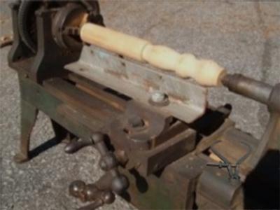
Figure 2b
The background image was given as the starting point for this scene. The spherical environment selected was a parking lot, from a high dynamic range (HDR) photography file. The reflections in the CAD model come from that environment and sort of resemble the rusty lathe bed. After the camera was positioned to locate the caliper on the bed of the table, the environment was rotated to cast shadows to match those in the background image. That wasn’t enough, so a directional light was added to simulate the sun and positioned to cast the right shadows from the caliper.
If the background is a flat image as in Figure 2b or 2c, the software keeps track of what the camera is pointing at and positions the background image opposite of that target. The result is that as the camera position changes, a different view of the 3-D model appears while the background image remains static. To put it another way, the background image is locked relative to the camera and floats around the 3-D model.
To align the model so that it looks right with respect to the background image, the camera that is looking at the model has to be positioned in the same place as the camera that took the background image—with the same lens, too. While moving the camera around to achieve this, the CAD jockey can find the model’s rotation to be disconcerting. All of the motions seem reversed somehow.
After you get used to that, it is time to change the rules. If the background image is a spherical environment—as opposed to flat image—then both the model and the spherical environment remain stationary while the camera moves around. The software never allows the camera to get outside of the spherical environment.
Using a spherical environment for a background image has some merit. The background seems to change in a realistic way as the camera moves around the model. It is an intuitive way to set up a scene and is very handy for setting lighting and shadow directions.
Being the picture is not really what a spherical environment was invented for. Rather, spherical environments provide lighting and reflections for the surfaces of the 3-D model. When the spherical environment is used as a background image, the 3-D model’s positioning with respect to the equator of the spherical environment can be limiting; many orientations result in unwanted distortion of the background image.
The calipers in Figure 2a look shiny because of the appearances applied to the model. Note that the spring is brushed stainless and the legs are matte steel. Those same appearances exist in Figure 1. We did add color to the surfaces to highlight the different components. Yet the shiny is gone in Figure 1. All we see is a pastel color.
That is entirely due to the environment in which the image was rendered. Figure 1 has a plain white background image and a plain white spherical environment. The shiny metal has nothing to reflect but uniform light.
In Figure 2b, the calipers appear to be rusty because they were rendered in a scene that reflected the background image. In Figure 2c, the caliper’s surfaces were rendered in a scene that reflected the wood grain countertop.
The software studio creates the light rays coming from the scene by using the spherical environment for both the lighting and the image to reflect. In setting up for Figure 2a, we rotated the environment so that the light cast nice shadows on the legs of the caliper. If additional lighting sources are required, they can be added to the scene just as a photographer would set up lights in a real-world studio.
Lights create shadows, but only if something is there to catch the shadow. The software I’m using supposes that the background image is so far away from the 3-D model that it will not catch any shadows from it, no matter where it is positioned. Shadows are cast onto model surfaces or onto the software studio’s floor. That floor can be relative to surfaces or planes at a controlled distance. In Figure 2c the studio floor was positioned on a plane in the caliper model. That plane touches the spring and the ends of the two legs. The environment was rotated so that the angle of the shadows cast onto the studio floor matched the shadows in the background image. Prior to fussing with the lighting, we moved the camera and background image around the caliper model until the caliper appeared to be in a logical place in the scene. The lens on the camera was adjusted to get the caliper to look like it belonged there.
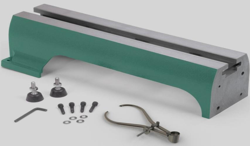
Figure 2c
The shadow under the caliper is cast onto a floor that is aligned with a plane that touches the caliper where it would rest if it were resting on a floor. The light for the shadow comes from a “shadow box” HDR spherical environment. Again, the environment was rotated to match the stationary shadows in the background image. The socket head cap screws tell that a very wide-angle lens was used to capture the background image. The lens selected for the camera view of this model does not quite match, does it?
Note that it is possible, perhaps even sometimes practical, to replace the software floor with a 3-D model of a floor and use that to catch the shadows. The same technique allows the casting of shadows onto the background; that is, don’t use the software background image, but instead put an image of the background on a 3-D model of the background.
Technology limits the time it takes to create images like Figure 2a. If the hardware is quick enough and the software able, we could spin the model and watch the reflections and shadows move. That is not practical on a typical CAD workstation, so we’ve selected levels of rendering quality for the task at hand.
The significant bit of hardware is the graphics card. The more it can do, the prettier the display while moving the model. Most graphics cards can deal with OpenGL rendering commands, which takes care of images like Figure 1. The 3-D model will “spin” easily with the mouse. If the graphics card is able, RealView functionality can resemble Figure 2. The spinning model looks shiny, but the shadows will be lacking.
Figure 4a was produced with OpenGL instead of RealView. The colors I selected are intended to identify the various components in the assembly. If the graphics card can’t handle the OpenGL commands, then the CPU is tasked with calculating all of the highlights and shadows, which results in slow response to the mouse.
Other factors affect response time as well. Figures 2a, 2b, and 2c images were rendered using a stationary software studio. Anytime the scene changes—the model moves, the lighting moves, the environment moves—the image must be repainted, and that can take seconds or many minutes for each frame, even in preview mode. Figure 2a took eight minutes to render on my laptop.
Advanced computing technology can speed things up. Compare Figures 2a, 2b, and 2c to Figure 4b, which renders in real time on my laptop. I can spin this model and see that it is metal all of the time. I have a better-than-entry-level graphics card.
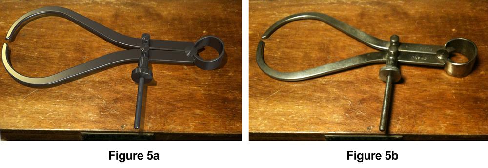
Figure 5a represents the final touches to the production presentation. It is a synthesized image using a merge of images from a real photo (JPG) and a CAD-generated (PNG) image. Figure 5b is a photograph of a real caliper sitting on a real box. We offer this comparison as a challenge to those who’d like to spruce up Figure 5a to make it look more like 5b.
Gerald would love to have you send him your comments and questions. You are not alone, and the problems you face often are shared by others. Share the grief, and perhaps we will all share in the joy of finding answers. Please send your questions and comments to dand@thefabricator.com.


The Fabricator is North America's leading magazine for the metal forming and fabricating industry. The magazine delivers the news, technical articles, and case histories that enable fabricators to do their jobs more efficiently. The Fabricator has served the industry since 1970.
start your free subscription
Easily access valuable industry resources now with full access to the digital edition of The Fabricator.

Easily access valuable industry resources now with full access to the digital edition of The Welder.

Easily access valuable industry resources now with full access to the digital edition of The Tube and Pipe Journal.

Easily access valuable industry resources now with full access to the digital edition of The Fabricator en Español.
In this episode of The Fabricator Podcast, Caleb Chamberlain, co-founder and CEO of OSH Cut, discusses his company’s...


