


Contributing Writer
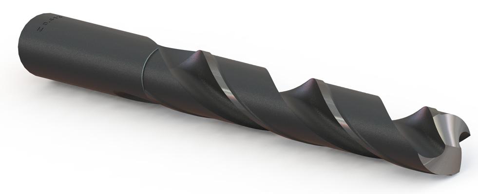
Figure 1
A jobber length twist drill is shown. This is letter size Z.
Editor's Note: If you would like to download the 3-D CAD files associated with this column, click here.
In this season of sharing we offer the jobber length twist drill shown in Figure 1.
The CAD modeling point of view shows some challenging features that need to be represented. Of particular note are the chisel point, relief lands on the cutting edges, and the runout of the flutes at the shank. To keep it interesting, the model has configurations to cover all of the letter drill sizes from A-Z (see Figure 2). Instead of 26 CAD files—one for each drill size—we need only one to populate our drill index.
With this twist drill model as a starting point, a CAD jockey could update it also to include a number of drill sizes by updating the Design Table. That’s simply data entry into a spreadsheet.
Because of the geometry, however, this project represents a significant amount of work. In terms of payback, a twist drill model might be useful for visualization in an assembly. Or if you’re in the business of manufacturing drill bits, this sort of model would be important to be able to create. For our purposes, this model is a handy way to discuss an approach to using surface modeling tools and perhaps reveal some CAD tricks you can apply in your other projects.
We encourage you to download and play with the model in order to fully appreciate the nuances of sequence and intrigues with extending and trimming.
To outline a plan for modeling, we begin by segmenting the model into groups of features. We’re looking for a foundation and progression in modeling steps. In the case of the drill bit shown in Figure 3, the main features are the shank, flutes, and tip.
As a starting outline of work, we propose:
The last item governs our selection of CAD techniques. We want to avoid dimensions that are not table-driven. To the greatest extent possible, new features will be sized based upon pre-existing features. That keeps them nice and flexible relative to each other.
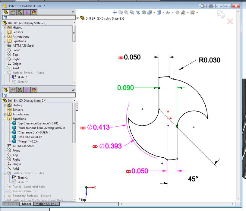
For this demonstration, we model the flutes and then cap them off with the drill point and shank. To model the flutes, we start with a sketch that represents a cross section of the flutes (see Figure 4a). The cross-section sketch allows us to define the drill size, clearance diameter, margin size, web width, and flute geometry. All of those dimensions are linked to equations or table-driven, so we take the time to rename them to identify their purpose.
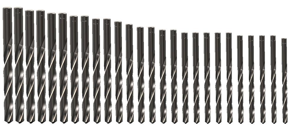
Figure 2
A Design Table in the drill model creates 26 configurations, one for each size of letter drill.
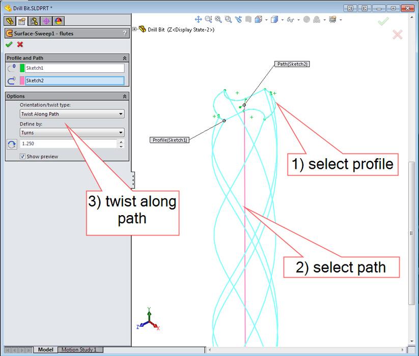
In addition to the cross-section profile sketch, we need a path sketch that represents the length of the fluted section of the drill. As shown in Figure 4b, the combination of path and profile is used to create a surface sweep with 11⁄8 turns of twist. For this demo, all of our drill bits will have the same amount of twist. If that were not the case, we could add the twist rate to the Design Table.
Turning to the drill bit’s point, we consider the fabrication method—twist drill sharpening—as we select our CAD modeling method. Drills are held against a grinding wheel at a compound angle and rotated. We want to duplicate that conical swoop.
To model a 10-degree helical relief land behind the cutting edge of the drill, we need a helix. A helix needs a circle. A circle needs reference geometry, i.e., a plane. (Here is a tip: Reference geometry—plane and axis—is intensely used in surface modeling, so you should become proficient with creating those items!)
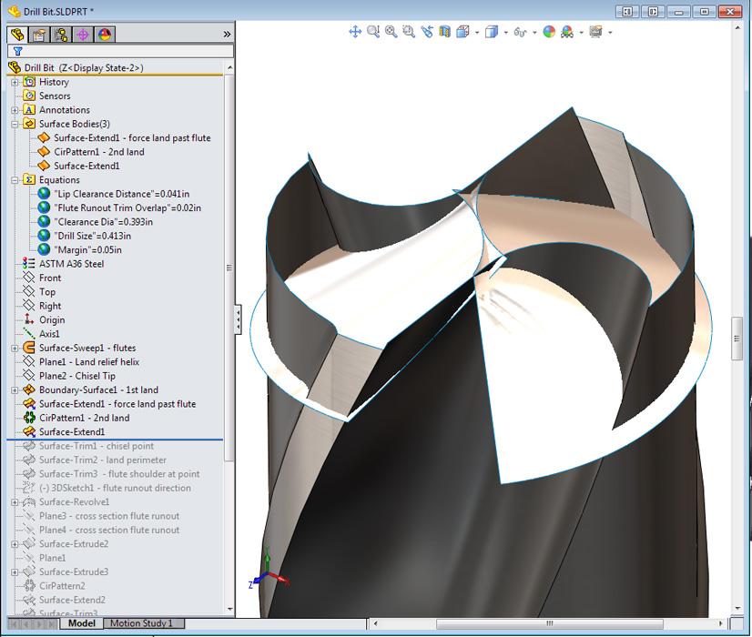
Figure 5a shows the result of creating a boundary surface using the helix for one of its edges, making a circular pattern to have a pair of intersecting lands.
The drill’s chisel point is the result of two intersecting land faces. So we now know trimming is in our future. In fact, the entire perimeter of this land face will be trimmed, so we won’t put a lot of work into modeling the other three edges.
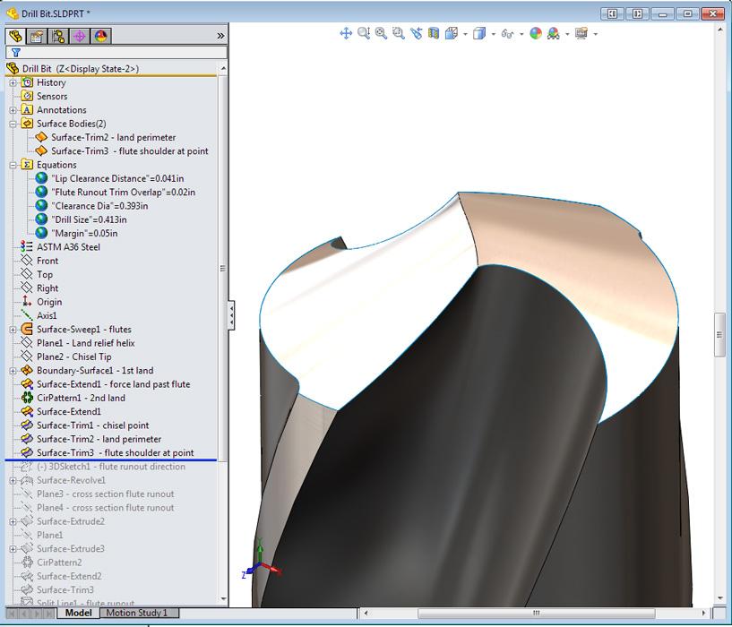
Figure 5b shows the result of trimming away the overlapping faces to create a drill’s land face, chisel point, and primary cutting edges.
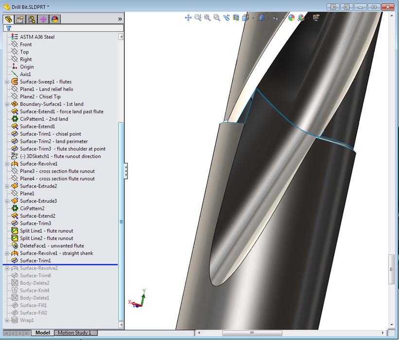
At the other end of the drill, we need the flutes to run out of the drill’s shank. Because of the twisted sweep trick used to create the flutes, the bit has no clean edge to extend to create the floor of the runout. We can create our own “edge” from the intersection curve between a plane and a flute. That process is repeated for the other flute’s runout.
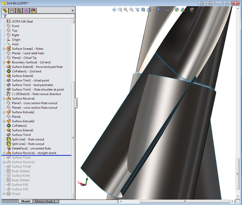
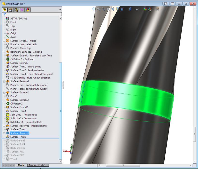
As shown in Figure 6a, a surface revolve works great for the drill’s shank. If one needed tapered shank drills, this would be one of the sketches to edit. We now can trim the runout faces with the shank’s face, as shown in Figure 6b.
As we progress in the modeling of surfaces, we want to avoid gaps as well as overlapping faces. Because of the method used for creating the runouts, the CAD jockey needs to trim away faces from the “interior” of the shell that we’ve created so far.
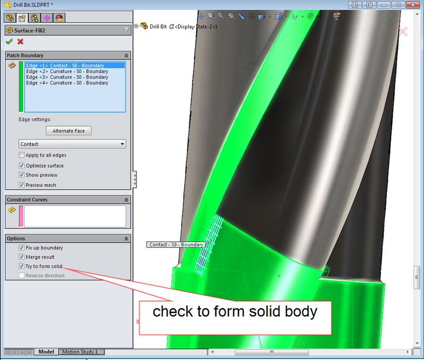
At this point, we’re almost finished. A few little holes in the drill surface still need to be closed. For example, the runout face has a missing corner. As shown in Figure 7, the trick is to think temporary. That is, create a surface, extend the edge up to that surface, and then delete the surface.
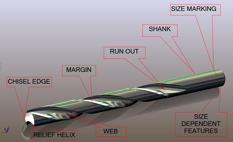
Figure 3
Consider all aspects of the final model when planning the starting point. Our starting point will be the flutes.
That leaves just two little triangular holes to fill. Surface fill works great for both. The trick with the last one is to check the Try to Form Solid box (see Figure 8). That converts the surface model into a solid body—if there are no gaps or overlapping faces.
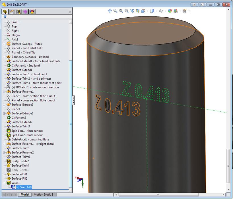
We like the conversion to solid body because of the convenience of the Wrap tool. That’s how we emboss the drill’s size into the shank (see Figure 9). Note that information found in the Design Table drives the text used by the Wrap.
Our next project is to model the drill index box so that we have someplace to store all of these drill bits.
Davis uses CAD software to design and develop products for his clients at www.glddesigns.com. He is a former owner and operator of a job shop from 1984 to 2004.
Gerald would love to have you send him your comments and questions. You are not alone, and the problems you face often are shared by others. Share the grief, and perhaps we will all share in the joy of finding answers. Please send your questions and comments to dand@thefabricator.com.


The Fabricator is North America's leading magazine for the metal forming and fabricating industry. The magazine delivers the news, technical articles, and case histories that enable fabricators to do their jobs more efficiently. The Fabricator has served the industry since 1970.
start your free subscription
Easily access valuable industry resources now with full access to the digital edition of The Fabricator.

Easily access valuable industry resources now with full access to the digital edition of The Welder.

Easily access valuable industry resources now with full access to the digital edition of The Tube and Pipe Journal.

Easily access valuable industry resources now with full access to the digital edition of The Fabricator en Español.
Seth Feldman of Iowa-based Wertzbaugher Services joins The Fabricator Podcast to offer his take as a Gen Zer...


