


Contributing Writer
 |
Like many other software tools, CAD continues to evolve at the speed of . . . real time. Even though we think the world moves at a faster pace each day, a second is still a second, an hour is still an hour, and real time is what matters in the world of manufacturing.
Some technologies have advanced so much that we can simulate a finished project in real time before starting to work on it. These technologies don't change, suspend, or alter the passage of time, but they do allow you to visualize a finished proj-ect such as a robotic workcell. Working forward, you can build a working CAD model of the workcell and run simulation software alongside it to animate the workcell. This allows you to see and visualize the animated design completely before constructing the project.
The technology available today in robotic simulation software paired with a CAD solid modeling package can allow you to plan, design, and integrate accurately a fully functional and automated project. You no longer have to wait and see the end product only to find out that the equipment capability or estimated cycle time did not yield the desired result.
Simulation software on the market provides accurate cycle time and trajectory information, allowing you to see programs graphically as you execute them on your computer screen. This usually is done through a virtual robot controller. Some controllers provide optimization tools to assist in achieving peak performance. They provide accurate line-by-line motion cycle time calculations, and the robot trace shows the actual robot trajectory (path) as a plot in the workcell. This plot allows you to determine the exact reach required to tend all of the equipment efficiently. The goal is to maximize machine tool utilization by loading and unloading the machines in the same time or less time than the longest machine cycle time.
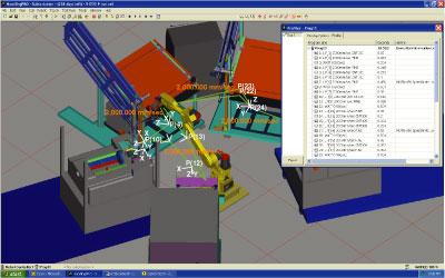 |
| Figure 1 Simulation software provides two views: a horizontal view, which allows you to visualize the equipment at eye level, and a plan view (shown here), which provides an isometric view of the workcell. The robot's motions are shown in green. The window at the right shows the program steps listed line by line and the time needed for each action on the virtual robot controller. |
When used in conjunction with the solid model of the machine tools, estimators, engineers, and customers can visualize the entire project before placing an order for anything. A virtual layout lets you see if the cell generates the results you expect.
Simulation software has key features that engineers use to focus on each of the phases of the life cycle for the design and execution of an automated system. Typical phases include concept, design, build, and programming. A good simulation package has capabilities that assist in several of these phases. For instance, during the concept and design phases, you will need to import the robot into your model, which enables you to determine that the reach of the robot meets the workcell's requirements. In the programming phase, you will want to move the robots over the equipment to confirm the cycle time.
During the initial and final concept phases of design, engineers and customers typically want to see they have chosen the right robot for the application, and then verify that the robots and the equipment layout can meet the reach and cycle time requirements. This is accomplished in several steps.
Cell Simulation Phase. The first step is to create a complete 3-D parametric solid model of the cell, which typically includes just the machine tools and robots. Next the simulation software is interfaced and activated to bring the robots to life by programming them with a virtual robot controller. You can then run a trace of their path over the model of the equipment layout and actually see the robots move and tend the machines. This allows you to visualize the true virtual simulation of what lies ahead on the shop floor, leading you into the design phase.
Design Phase. In the design phase an engineer brings the tooling, fixtures, and other components of the cell into the model. The goal is to look far enough ahead and avoid costly mistakes before ordering materials and manufacturing anything. During this phase it is also possible to reduce the floor space needed and provide critical and accurate plant layout information before seeing the cell assembled for the first time. In addition, you can look for clearance problems or other interferences during the build phase of the project. Programming and electrical design also are completed at this stage.
The simulation software makes it possible for you to complete the programming work before the project is built. All steps should facilitate staying on track with a timeline for the project and avoiding costly, unforeseen problems during the build and start-up of the cell.
Program Generation and Optimization Phase. The final step is to use simulation tools to aid the offline generation and optimization of the necessary robot program. These tools allow you to get the cell working as soon as all equipment and components are complete and in place.
In fact, you can start running the cell before all the equipment is in place, as long as the robots are set up. The final simulation program is loaded directly into the robot controller, and programming the robots can be completed while the cell is still being constructed. You do not need to wait until everything else is complete and in place. If you are integrating equipment that is currently being used in production, you don't need to stop production until the cell is complete. As you make the transition from your previous manual process to the new, automated process, you can use a hybrid approach (part manual, part automated) until you complete the workcell.
Simulating the actions of a workcell should result in a mutually advantageous project for both the integrator and the customer. The integrator should benefit from utilizing design tools and disciplines that are key to engineering a robust system that ensures the project will work right immediately. The ability to see ahead should reduce or eliminate the need for engineering changes.
The additional cost factor that traditionally is built in to cover unforeseen mistakes or omissions is no longer a concern for either party. The customer benefits from a cost-effective cell that produces its products in a timely manner without any compromise.
Some simulation products are keeping up with the expanding range of automation processes, such as plug-ins for material handling and removal, arc welding, palletizing, and painting. Each plug-in has unique features that enable efficient program generation for each respective process. Using these simulation products during the design phase allows you to make the most of your time . . . in real time.
Eric Patty is the president of Wauseon Machine and Mfg. Inc., 995 Enterprise, Wauseon, OH 43567, 419-337-0940, www.wauseonmachine.com. FANUC Robotics contributed to this article.

The Tube and Pipe Journal became the first magazine dedicated to serving the metal tube and pipe industry in 1990. Today, it remains the only North American publication devoted to this industry, and it has become the most trusted source of information for tube and pipe professionals.
start your free subscription
Easily access valuable industry resources now with full access to the digital edition of The Fabricator.

Easily access valuable industry resources now with full access to the digital edition of The Welder.

Easily access valuable industry resources now with full access to the digital edition of The Tube and Pipe Journal.

Easily access valuable industry resources now with full access to the digital edition of The Fabricator en Español.
Seth Feldman of Iowa-based Wertzbaugher Services joins The Fabricator Podcast to offer his take as a Gen Zer...


