


The wiper die’s role and rake
Optimizing the wiper die’s function
The mechanical aspects of rotary draw tube bending haven’t changed since modern tooling was developed more than five decades ago. The machines have become much more complex and tooling is available in a greater variety of alloys, but their roles haven’t changed. The machine’s role is to advance and hold the workpiece and control the tooling; the various tools work together to make repeatable, high-quality bends.
While no tooling component is more important than any other, likewise none is less important than any other. Each requires proper attention to how it is set up to ensure the best possible bend. Although the wiper die’s purpose might not be obvious, it prevents two types of bending defect when set properly.
Getting to Know the Wiper Die
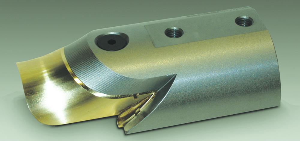
At first blush the wiper die is a simple tool. Often the wiper is a solid block machined to fit the gap between the bend die and the back tangent of the tube. Frequently the wiper die is an uncomplicated, two-piece assembly in which the leading edge is a disposable insert.
The essential element of wiper die design is the feathered edge—the knifelike edge formed by the convergence of the tube cavity with the sweep of the radius face. The rest of the tool is nothing but mass to support the feathered edge and provide sufficient surface area for mounting it to the machine.
The wiper die serves two functions in the rotary draw process. The first is to prevent a hump from forming at the trailing end of the inside radius of the tube bend. As the tube is drawn into the bend, it becomes plasticized at the point of bend. The plasticized material behind the line of tangency flows into the curve of the bend die cavity sweeping away from the back tangent of the tube. Upon completion of the draw, if this deformation exceeds the elasticity of the tubing material, it will set as a hump, or a series of small humps, at the end of the bend. Fixturing a wiper die in the gap between the bend die and the tube stops the deformation by blocking the flow of the material.
Because all tubing materials have some elasticity—that is, the property of resuming its original shape when stress is relieved—it is not necessary to fixture a wiper so that it fills the entire gap to prevent a terminal hump from forming. A wiper can be raked, meaning the feathered edge is angled away from the line of tangency, to block the flow of material only before it passes the point of elasticity (see Figure 1). This lengthens the wiper’s service life. A wiper set at no rake blocks the flow of all the material, and the resulting friction accelerates wear.
However, raking a wiper die to extend its life can be at odds with its second function: full containment of the tubing material at the point of bend when bending under high pressure. High radial pressure as applied by the pressure die is not necessary in most draw bending applications if the mandrel nose is used aggressively, but high pressures are necessary for exceptionally hard materials such as 304 stainless steel, titanium, or even mild steel on an extremely tight centerline radius. These materials resist the compression that occurs as the intrados thickens during the draw. If the flow of material is not completely contained by tooling at the point of bend (the mandrel, the pressure die over the outside radius of the bend, the bend die over the inside radius ahead of the line of tangency, and the wiper also over the inside radius behind it), compression will buckle the tube.
Therefore, the tubing material (and to a lesser extent the bend specifications) dictates whether a wiper can be raked. These factors also dictate the tool’s geometry, because a feathered edge designed to be raked for low-pressure bending will not perform well at zero rake under high pressure, and vice versa.
To Rake or Not to Rake
Although some high-pressure bending applications do not tolerate any wiper rake, the wiper should be set up with as much rake as possible to reduce drag on the tube and increase wiper life. Because the purpose of the wiper is to stop a terminal hump from forming on the inside radius upon the completion of the bend, the wiper needs to suppress only that amount of the height of the terminal hump that exceeds the tubing material’s point of elasticity. Raking the wiper extends its service life by reducing the force of the terminal hump against the feathered edge. Otherwise, at zero rake the feathered edge must suppress the entire height of the terminal hump, including that portion of its height that the tubing’s elasticity will reduce naturally on its own at the completion of the bend.
Material variations and other considerations mean that, in many cases, the wiper must be set to less than the ideal rake. For materials with little elasticity, especially stainless steels, this means zero rake. Such inelastic materials resist compression. Therefore, the plastic point-of-bend region of the intrados requires complete containment by tooling both ahead of the line of tangency and behind it. The bend die cavity and the wiper die cavity, when the wiper is set at zero rake, provide this containment.
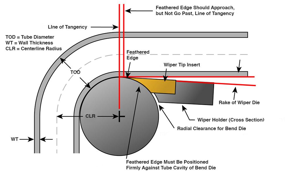
Figure 1
A two-piece wiper die consists of a body (wiper holder) and a disposable working surface (wiper tip insert), which has a feathered edge. When the wiper die is set properly, the feathered edge prevents two types of bending defect: terminal humps and a buckled intrados.
Note that for high-pressure, zero-rake applications, solid-body wiper dies may be preferred to two-piece wipers. In either case, the feathered edge should be cut with offset geometry, sometimes called an aero-cut, instead of the standard simple-sweep geometry that accommodates raking.
Setting the Wiper Gap. Instead of an angle, rake often is expressed as a measure of the gap between the back edge of the wiper and the tube’s OD. However, expressing rake as this particular distance can be problematic.
First, it focuses the machine operator’s attention on the nonworking end of the wiper. Setting this gap at the correct distance is no guarantee that the wiper’s feathered edge is properly nested in the bend die cavity. Even if the feathered edge is in contact with the bend die cavity, it may not be in the correct position relative to the line of tangency.
Second, variations in wiper length result in variations in rake if this gap distance is held constant from one tool to the next. This may not affect bend quality if the result is less rake; the likely outcome is that the wiper won’t last as long. But, if the result is excessive rake, terminal humps can appear.
Setting the Wiper Angle. An alternative to using the gap is to use the distance between the line of tangency and the feathered edge. After the operator determines the proper rake angle, with the feathered edge properly nested in the bend die cavity, he takes a linear measurement between the feathered edge and the line of tangency along the circumference of the bend die cavity.
When the time comes to replace the wiper, the operator nests the new wiper’s feathered edge in the bend die cavity flush with the line of tangency. He then slowly rotates the wiper away from the line of tangency, maintaining secure contact between the feathered edge and the bend die cavity, until the feathered edge reaches the distance he measured initially.
By this means, the established rake for an application can be repeatedly set without regard to variations in wiper die design.
About the Author
About the Publication

subscribe now

The Tube and Pipe Journal became the first magazine dedicated to serving the metal tube and pipe industry in 1990. Today, it remains the only North American publication devoted to this industry, and it has become the most trusted source of information for tube and pipe professionals.
start your free subscription- Stay connected from anywhere

Easily access valuable industry resources now with full access to the digital edition of The Fabricator.

Easily access valuable industry resources now with full access to the digital edition of The Welder.

Easily access valuable industry resources now with full access to the digital edition of The Tube and Pipe Journal.

Easily access valuable industry resources now with full access to the digital edition of The Fabricator en Español.
- Podcasting

Seth Feldman of Iowa-based Wertzbaugher Services joins The Fabricator Podcast to offer his take as a Gen Zer...
- Trending Articles
1
Zekelman Industries to invest $120 million in Arkansas expansion

2
3D laser tube cutting system available in 3, 4, or 5 kW

3
Corrosion-inhibiting coating can be peeled off after use

4
Brushless copper tubing cutter adjusts to ODs up to 2-1/8 in.

5
HGG Profiling Equipment names area sales manager
