


Graduate Research Assistant, ERC/NSM
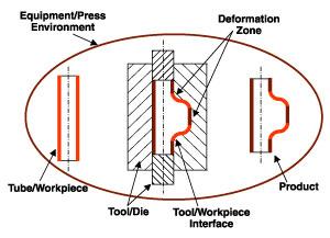
Figure 1. Like stamping, the hydroforming process uses a press system and tooling to deform a workpiece.
A typical tube hydroforming system is shown in Figure 1. Within this system, a host of factors must be taken into account, from starting tube geometry and material properties to the quality of the final part (such as thickness distribution and dimensional accuracy).
Each of these components plays an important role in the success of the process, and each must be addressed during the process development stage. Thus, the application of tube hydroforming technology must take the following into account:
This article discusses these points, along with how computer-aided simulation can aid a hydroformer in the process.
The quality of the incoming tube is critical for successful hydroforming. Material properties (material composition, weld type, yield strength, ultimate tensile strength, percent elongation, flow characteristics, etc.) and dimensions (such as diameter and thickness) of the tube must be determined based on the final part requirements and closely monitored during the manufacturing process.
To obtain realistic information about the material properties of the tube, a test procedure that is similar to the hydroforming process must be used. A sketch of such a bulge test used at The Ohio State University is shown in Figure 2. In this test, the tube is locked on both ends and stretched freely using hydraulic internal pressure. Several parts made of type 304 stainless steel bulged under different pressures (see Figure 3).
For a specific tube material and thickness, the pressure and the maximum bulge diameter are measured at various pressure levels. This data is used with a proprietary computer program to predict the flow stress of the tube material in function of strain in the form of an equation. This equation then can be used with a finite element method (FEM) program to simulate the tube hydroforming process.
Friction conditions in hydroforming are critical, especially for parts requiring substantial axial feeding. In such cases, lubrication is used to reduce the sliding friction and prevent sticking and galling to reduce tool wear, axial forces, and excessive thinning. Lubrication also becomes a critical factor during the calibration stage, when the tube cross section is stretch-formed to the final dimensions (see Figure 4).
A good lubricant must:
No single lubricant can fulfill all these requirements, so a compromise must be made in selecting lubricants. Various tests can be used to evaluate one or more of the lubricant's characteristics in the preceding list, the most important trait being lubricity, or coefficient of friction.
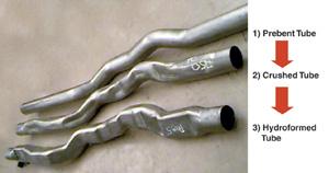
The starting tube geometry for hydroforming may be straight, or it may have a prebent or preformed shape, depending on the complexity of the final product to be manufactured (see Figure 5). In some applications, certain sections of the part may be crush-formed during die closure and later calibrated to the final dimensions of the die surface. To achieve fully plastic deformation in the whole part, and thus to reduce the springback, the tube perimeter should be made slightly smaller than the die geometry in each cross section.
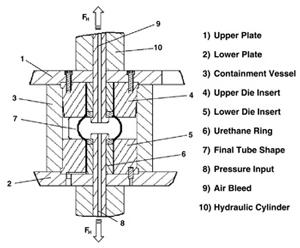
Figure 2. A detailed view of the press system features and die components hints at how they interact to form the component.
The strains in the bent tube affect deformation and thinning during tube hydroforming and determine the thickness and strength distribution in the final part (this is considered during the design stage so that the formed part has the desired properties before subassembly).
Thus, in bending tubes for hydroforming, manufacturers must avoid excessive wrinkling in the compressed part of the bent tube so that no wrinkles occur on the hydroformed part. Manufacturers also must estimate the thinning that occurs on the stretched parts of the tube to determine whether the selected tube thickness is adequate to provide the minimum thickness requirements of the part after hydroforming.
Furthermore, it often is necessary to orient the tube before bending so that the weld line is in the neutral zone and is not subject to tension or compression during deformation.
The main functions of a hydroforming press are to open and close the die and to provide a clamping load during the forming process to eliminate elastic deflections and die separation. Additional units that are required to carry out the process include axial force cylinders and a pressure intensifier.
Currently, hydraulic presses are used to provide large clamping forces during the process. These presses usually involve a large capital investment. However, several research institutes are trying to develop low-cost equipment that uses several steps to open and close the tooling and provide the clamping load.
In one such design, the ram with the upper die half is actuated up or down with a small cylinder. After the ram reaches its bottom dead center position and the dies are closed, two distance blocks are pushed with pneumatic or hydraulic cylinders between the ram and the press frame. Several short-stroke cylinders then press the bolster with the lower die half upwards, which eliminates any clearance between the die halves. This design allows a fast stroking rate but requires less power to close, clamp, and open the dies.
Displacing large fluid volumes to open and close the dies, moving the part in and out of the tooling, and filling and pressurizing the tube are several factors that reduce the cycle time.
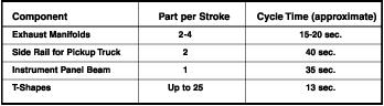
However, one of the main factors limiting the production rate is the bending and preforming operation. Therefore, to increase the production rate, several bending machines may be used to supply parts to the tube hydroforming process, or several parts can be formed at one time. Some sample production rates are given in Figure 6.
To conduct hydroforming successfully, manufacturers must select appropriate machine settings, that is, pressure versus time and axial feeds versus time. Only then is it possible to avoid defects such as wrinkles from excessive axial feed or fracture caused by excessive pressure. These machine settings are difficult to select based on experience alone, especially when developing new dies and a new forming process. As a result, too much costly and time-consuming trial and error may be required to establish the correct machine operation.
Therefore, it is better to conduct this trial and error during process development with computer-aided techniques that simulate machine operation and tube deformation.
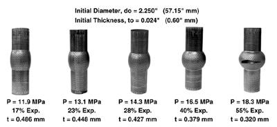
Figure 3. In this experiment, a length of SAE 1008 steel was formed with 2,654 PSI (18.3 MPa) of internal pressure.
Simultaneous application of internal pressure and axial feeding allows the tubular blanks to take the shape of the die. Tube material properties and formability determine whether the final part can be formed under the existing process conditions.
Initial estimates of the process parameters (such as internal pressure, axial feeding, and counterpressure) can be obtained from analytical calculations or computer simulations to reduce the development time. Various software packages can simulate the tube hydroforming process.Internal pressure usually is described by a pressure-time function, but this may cause stability problems in some cases. However, using a flowing volume-time function (of the pump) instead of a pressure-time function eliminates the stability problem. The volumetric flow option is available in a few finite element codes within computer programs such as Indeed, LS-Dyna, and Pam-Stamp.
For reliable predictions of formability conditions in tube hydroforming, accurate material data (flow stress, thickness, diameter, and anisotropy) and process information (internal pressure, axial feeding, counterforce, and friction) need to be provided to the computer simulations. The input data also should include the strain history (hardening of the material during the bending and preforming).
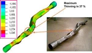
Predicting the thinning distribution in a structural component made of low-carbon steel (1008) using Pam-Stamp is shown in Figure 7. In this hydroforming process, a 2.5-meter-long, 120-millimeter-diameter, 3-millimeter-thick tube was bent, crushed, and hydroformed to the final dimensions. Each step in the manufacturing process was simulated, starting from the bending operation, and the strain history was carried over to the next step to improve the accuracy of predictions.
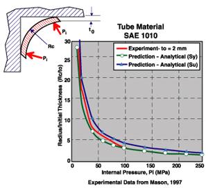
The finite element analysis predictions agreed well with actual measurement of the part, provided by Dana Corporation. An application example of analytical models is shown in Figure 8. Tube corner radii in this example are calculated in the function of internal pressure using analytical models. These models yield results in good agreement with the experimental results.
The method of adaptive process simulation is still in a development stage and aims at estimating the pressure-versus-time and axial feed-versus-time curves in a single simulation. This information is necessary to set up the press operation for successful hydroforming of a given part.
At every time increment of the finite element simulation, the program reads the necessary current data from the simulation model. If any node has a negative velocity vector (toward the centerline of the tube), it is detected as the beginning of wrinkling. (Another way to detect wrinkling is looking at the slope of the part surface).
Consequently, as a correctional measure, the program increases the internal pressure while simultaneously stopping the axial feeding of the material.
If wrinkles have been removed, the internal pressure is kept constant while the material feeding is resumed. Using geometric criteria such as velocity or displacement is a very simple way to detect wrinkling.2Increasing the internal pressure expands the tube and eliminates wrinkling. Thus, at the next step, it is possible to feed more material into the die to allow further expansion of the tube into the die cavity.
If, after this feeding, step wrinkling recurs, the pressure then is increased. This procedure is carried out in the computer with FEM simulation. This makes it possible to obtain the best pressure-versus-time and axial feed-versus-time curves in a single simulation.
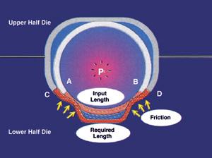
Figure 4. A capable lubricant is just as important as a well-designed tool.
Research and investigation of tube hydroforming in industry and at universities during the past five years have led to a state-of-the-art process that allows the manufacture of a variety of workpieces in a high-volume production environment.
However, compared to conventional stamping, the tube hydroforming process is still relatively new, so there is no extensive knowledge base for tool and process design. Therefore, a clear understanding of computer modeling will help engineers to develop reliable control strategies for the axial feed, internal pressure, and counterforce as functions of time to improve the material shaping capabilities of hydroforming.
Because of the high pressures involved in tube hydroforming, trials cannot be made using soft tooling. Dies have to be manufactured from steel with certain hardness and coating specifications, and modifications are costly. Thus, the potential of tube hydroforming can be improved by reducing trial and error in tool and process development, and this can be achieved through a better understanding of the interactions among the process parameters using computer modeling.
A variety of predictions (thickness distribution, internal pressure, clamping force, friction forces, and springback) formulated by process modeling helps to determine any possible shape defects and bursting in the planning phase and allows designers to improve their die design before the hard tooling is manufactured.

Professor Emeritus and Director - Center for Precision Forming

The Tube and Pipe Journal became the first magazine dedicated to serving the metal tube and pipe industry in 1990. Today, it remains the only North American publication devoted to this industry, and it has become the most trusted source of information for tube and pipe professionals.
start your free subscription
Easily access valuable industry resources now with full access to the digital edition of The Fabricator.

Easily access valuable industry resources now with full access to the digital edition of The Welder.

Easily access valuable industry resources now with full access to the digital edition of The Tube and Pipe Journal.

Easily access valuable industry resources now with full access to the digital edition of The Fabricator en Español.
Seth Feldman of Iowa-based Wertzbaugher Services joins The Fabricator Podcast to offer his take as a Gen Zer...


