


Contributing Writer
 |
In the manufacture of tubing by continuously roll forming and welding, the cost of the finished product is directly related to the production rates which are often controlled by the maximum speed of the welding process. The logic is simple: Increasing tube mill speed while maintaining weld quality is advantageous.
This article discusses high-amperage, high-frequency pulsed arc welding power supply technology that the manufacturer claims has increased tube mill weld speeds up to 300 percent in European installations.
Tube mills produce thin-wall pipe and tube by taking a continuous strip of material and roll forming along the length of the strip until the edges meet and mate together at a weld station. At this weld point, the welding process melts and fuses the edges of the strip together, and the material exits the weld station as welded tube.
The obvious question becomes, "How can tube mill weld speed be increased?" With the current atmosphere of frugality and cutbacks, the manufacturing engineer of a tube producing facility has become familiar with many aspects of the manufacturing process, including manufacturing and automation principles, tube mill roll forming, weld box design, strip edge quality, materials technology, and quality control.
However, a surprising number of engineers investigate the maximum potential of the mill mechanicals and ignore the main bottleneck: the welding process.
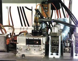
Many tube producers use tungsten inert gas (TIG) arc welding as the final step in the tube making process. In TIG welding, an arc is struck between a pointed tungsten electrode and the material to be welded. The heat of the arc — up to 25,000 degrees Fahrenheit — melts the weld seam, which becomes almost invisible after later processing.
The tungsten electrode, the arc, and the weld are covered with a shield of inert gas that flows from the weld torch. The shield gas displaces air and moisture from the weld area, helping to minimize oxidation of the weld.
The tube mill speed is increased until the molten material no longer flows together at the weld joint. At that point, the tube mill operator often notes the weld speed obtained, establishing the limits of the system for the specific material being welded. This way of thinking can be harmful to a company.
To increase weld speed, some companies have purchased multicathode welding systems. Dual or triple cathode systems have been available for some time.
In tricathode systems, three welding torches fire three separate arcs. The first arc preheats the tube material, the second arc makes the weld, and the final arc is often used to smooth the weld surface. This process can be complex for some companies.
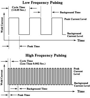 |
| Figure 1: Conventional arc pulsation involves using the power supply to rapidly alternate the weld current from a high (peak current) to a low (background current) value. |
The new single-cathode TIG beam technology has been developed and refined for the tube and pipe industry over the last two years in Germany. The solid-state linear power supply uses rapid response transistors and signal conditioning to provide 300, 600, or 900 amps of weld current at up to 10,000 pulses per second.
The rapid transition from a high current value to a low current value pulsing at high frequencies helps to reduce the arc size. This results in a high-energy density arc which produces a smaller weld pool for the same amount of current. The smaller weld pool has high penetration and low surface tension.
Combining conventional arc pulsation with the increased energy density of the high-frequency pulsed TIG beam arc helps increase weld speed while maintaining weld quality.
Conventional arc pulsation involves using the power supply to rapidly alternate the weld current from a high (peak current) to a low (background current) value (see Figure 1). In some cases, materials and weld joints that are difficult to weld with a nonpulsed arc may be welded using a pulsed arc technique.
Arc pulsation involves four welding parameters: peak current, background current, pulse width (duty cycle), and pulse frequency. These parameters affect arc force and stability and the resultant weld speed and quality.
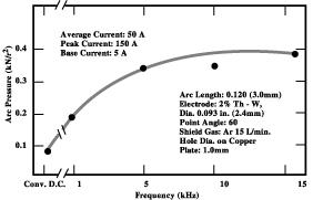 |
| Figure 2: This graph shows the relationship between arc pressure and pulse frequency. |
Peak Current, Background Current, and Pulse Width. The heat of a TIG arc can melt most metals in about 25 percent of the time it takes for the melt to solidify. The object of weld pulsing is to melt and solidify in step with the current pulsing.
The pulse width (the percentage of time that the peak current flows) is usually selected between 10 and 35 percent. Peak and background current are then chosen to give a balance of heat input to the material. Peak current is usually set at a value of 2 to 5 times the background current in accordance with the pulse width used:
Peak Current 600 amps at 35 percent pulse
width = 210
Background Current 200 amps at 65% pulse
width = 130
Average Weld Current 340
Pulse Frequency. Pulse frequency is usually chosen with reference to weld speed to ensure that the weld spots created by pulsing the current overlap each other by a minimum of 60 percent. Many tube producing facilities use an overlap of about 85 percent to give the weld a smoother appearance.
Following is an example:
Strip Material 304 stainless steel
Thickness 0.5 millimeter (.020 inch)
Weld Speed 20 meters per minute (65.6 feet per minute)
Assuming that the weld puddle width will be about 1.5 times the material thickness and that 85 percent overlap is required, the spacing between the weld pulses will be:
Pulse Spacing = Material thickness x 1.5 x 15 percent
= .020 x 1.5 x .15
= .0045 inch per pulse (IPP)
Pulse Rate = Weld speed (inches per second [IPS])/Spacing between pulses (IPP)
= 65.6 x 12/60 / 0.0045
= 2,915 hertz
Pulse rate increases as weld speed increases. In many cases, higher pulsation rates are used to gain the benefit of arc constriction. The power supply chosen for the tube mill should have adequate amperage, square wave current waveform, and sufficient pulsation rate capability so that weld speed increases are not restricted.
High-frequency pulsed arc welding has a pulsing rate of more than 500 pulses per second. The high-frequency switching produces an increase in arc pressure (seeFigure 2). Arc pressure and arc stiffness or stability are related, and, as the switching frequency nears 10 kilohertz, the arc pressure increases to nearly four times that of a steady direct current (DC) arc.
As a result, the arc cross section area decreases, and arc density and temperature increase.
The decline in the arc's physical size delivers a smaller weld pool and helps improve the weld depth-to-width ratio, which in turn has a positive impact — reduced porosity, smaller heat-affected zone (HAZ), etc. — on the material's mechanical properties or ultimate strength. This effect has also been noted with changes in pulse frequencies while maintaining the same average current or heat input.
Other effects of this pulsing method are alterations in microstructures, reduced microcracking, and reduced weld microporosity. In addition, deep penetrating welds can be made at some frequencies, while welds can be made wide and shallow with other parameters.
In general, the limitations of applying arc pulsation lie in choosing the correct weld parameters for a given material. Stainless steels and copper react very well to a condensed arc, while other materials will not perform as well with this process because of their sluggishness in molten form.
High-frequency arc pulsation produces an audible signal from the arc. For this reason, the weld box is usually enclosed to dampen the sound.
The higher density arc with a smaller weld pool surface tension allows for a corresponding increase in weld speed according to the ability of the supporting tube mill.
The key to increasing tube mill weld speed is to provide consistent roll forming of the strip material for edge presentation at a weld station. This allows the TIG beam welding process to maximize the mill output.
Weld speed depends on:
1. Strip material composition and weldability and certification tolerance limits.
2. Material surface contaminants.
3. Weld shield gas(es) used.
4. Strip edge quality.
5. Tube mill and/or weld box ability to provide consistent joint geometry with minimal gap or edge mismatch when presenting tubing to the welding arc.
6. Welding system power supply maximum amperage and duty cycle and high-frequency square wave arc pulsation ability.
Because of the factors not under the control of the welding system, maximum mill speed cannot always be achieved. Many instances exist in which two tube mills forming similar materials of identical dimensions are running at significantly different speeds because of the tube mills involved. However, high-frequency weld pulsation has been shown to help increase weld speed by about 25 percent on an average mill.
Increasing weld speed often reveals other limitations within the tube mill system. Other mill issues must also be considered:
1. What is the maximum running speed of the tube mill?
2. Can the mill offer good edge presentation to the welding arc at higher travel speeds?
3. What welding speed does the flying cutoff saw allow?
4. Will other downstream processes limit the maximum output of the tube mill?
These limitations can be investigated and improved to allow for new running speeds.
Minor changes in strip material may have a significant effect on weldability. Surface-active impurities such as sulfur, aluminum, and oxygen alter surface tension gradients in the molten weld puddle, thereby changing fluid flow and fusion zone patterns. Tube producers should recognize the importance of material specification tolerances.
On installation, optimum weld parameters are developed within the installation time available. The end user should investigate the effect of minor changes to each weld parameter — such as the weld pulsation parameters, arc gap, torch orientation, magnetic arc control extents, electrode material, grind angle(s) and finish, and shield gas mixtures chosen — to overall system output.
System design must be tuned to the specific needs and budget of the end user.
A correctly designed weld station can offer many benefits and thus can be critical to the operation of the system. Weld station design must consider the following functions:
1. Reproducible weld results at the weld point
2. Sound absorption
3. Torch position adjustment
4. Magnetic arc control
5. Ultraviolet arc protection
6. Welding seam view
Thought must also be given to mechanical adjustments and torch maintenance. Shield gas and waste gas control carry their own considerations. The tubing often carries a layer of atmospheric oxygen toward the weld zone that must be displaced before the welding arc impinges on the material.
Modern technology has revolutionized many manufacturing operations. In the current global marketplace, manufacturers are looking for ways to increase output, consistency, and quality.
For a company to increase its share of the market, or even to remain competitive, it must find more efficient and better methods of production. A willingness to test where the limits of new technology really lie can result in more and better product at a cost savings.

The Tube and Pipe Journal became the first magazine dedicated to serving the metal tube and pipe industry in 1990. Today, it remains the only North American publication devoted to this industry, and it has become the most trusted source of information for tube and pipe professionals.
start your free subscription
Easily access valuable industry resources now with full access to the digital edition of The Fabricator.

Easily access valuable industry resources now with full access to the digital edition of The Welder.

Easily access valuable industry resources now with full access to the digital edition of The Tube and Pipe Journal.

Easily access valuable industry resources now with full access to the digital edition of The Fabricator en Español.
In this episode of The Fabricator Podcast, Caleb Chamberlain, co-founder and CEO of OSH Cut, discusses his company’s...


