


Ph.D.
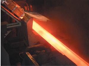 |
Controlling the wall thickness during the manufacture of seamless steel tubes and cast-iron pipe is critical in meeting specifications and minimizing scrap. Ultrasonic measurements typically are performed on tube or pipe at room temperature, many hours after forming is complete. At this point in the forming process, if dimensional specifications are not met, the feedback to the production system is too late to provide any benefit. The ability to perform measurements at high forming temperatures (up to 1,200 degrees C) and at high speeds (up to 5 meters per second) allows inspection during the production process, thereby providing much more immediate and effective feedback to the machine operator.
To avoid scrapping a tube or pipe because its wall is too thin, designers typically overdesign the wall to ensure the minimum thickness specification is met. This safety margin results in a significant waste of raw materials. Additionally, if the wall thickness is not constant over the tube length or around the circumference, product performance and customer satisfaction are less than optimal. An in-process measurement of thickness as a function of length, as well as tube eccentricity, allows the mill operator to make immediate corrections that reduce the amount of raw material required to meet specifications and to improve product quality.
The laser ultrasonic technique is a noncontact, remote measurement process in which lasers generate and detect ultrasonic waves. The laser ultrasonic process is a modification of the conventional transducer-based contact ultrasonic inspection. Instead of piezoelectric or electromagnetic acoustic transducers (EMATs), a pulsed laser generates an ultrasonic wave and a laser ultrasonic receiver detects the ultrasonic wave as it returns to the surface.1
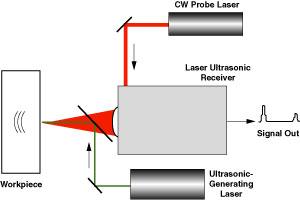 |
| Figure 1 The laser-based ultrasound process uses two lasers. One laser transmits a pulsed beam that generates an ultrasonic wave in a workpiece. A second laser transmits a continuous-wave (CW) beam that the laser ultrasonic receiver uses to determine the wall thickness. |
While laser methods for generating and detecting ultrasonic waves are quite different from transducer methods, lasers nevertheless can generate and detect the full spectrum of ultrasonic waves. Normal transducer-related geometries can be used, as well as familiar signal interpretation methods.
The laser ultrasonic process has several characteristics that are beneficial in tube or pipe production. First, the sensor does not have to be in contact with the workpiece, which allows measurements on hot or moving parts. Second, the in-process capability of laser ultrasonics allows real-time data collection for process control and optimization. Finally, higher-bandwidth ultrasonic waves can be generated and detected with lasers than with contact transducers, thereby increasing spatial resolution and providing added data for signal processing.
Laser-based ultrasonics measures the time of flight between pulse echoes (see Figure 1). This approach is also commonly used in transducer-based ultrasonics. Because the velocity of ultrasonic (sound) waves in the workpiece is usually known, the workpiece thickness can be determined easily.
The laser ultrasonic receiver shown in Figure 1 is a type of optical interferometer that converts nanometer-scale displacements (vibrations) measured at the surface into a change in electrical output signal amplitude, or strength. In early laser ultrasonic experiments, such interferometers required careful length stabilization and could process signals obtained only from mirrorlike surfaces. Newer adaptive laser ultrasonic receivers require no length stabilization and allow the processing of speckled signal beams received from rough surfaces. Another major advantage of these adaptive receivers is their insensitivity to noise at lower frequencies caused by workpiece vibrations that result from production equipment and airborne turbulence in the path of the receiver.
An inline wall thickness measurement system at the output end of a forming mill in a seamless steel tube production line is illustrated in Figure 2. It has a measurement head that contains beam delivery optics for the pulsed ultrasonic-generating laser, together with sensor optics for the remote, fiber-coupled CW laser ultrasonic receiver. The ultrasonic-generating laser, CW probe laser, and laser ultrasonic receiver are coupled to the measurement head with up to 30 m of fiber-optic cable.
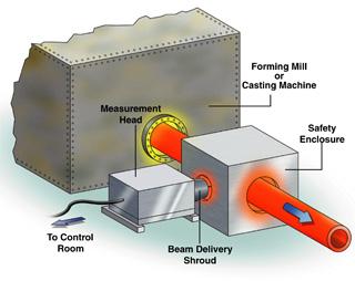 |
| Figure 2 The water-cooled measurement head is positioned close to the path of the hot tube or pipe as it exits the forming process. The measurement head contains beam delivery optics for the ultrasonic-generating laser and laser ultrasonic receiver. The lasers and ultrasonic receiver do not require close proximity to the workpiece. |
The measurement head is water-cooled for protection against the ambient temperature and transient heating by radiation from the hot tubes passing by the point of measurement. A flow of clean air also is provided to prevent dust and smoke from entering the enclosure or accumulating on the optical surfaces of the beam delivery system.
The measurement head is mounted on a platform at the exit of the forming mill. A beam shroud and safety enclosure around the tube path are included to prevent worker exposure to the laser beams. The standoff distance from the measurement head to the surface of the hot tube is set at about 45 centimeters. To be immune to changes in the lateral position of the tubes as they exit the mill at speeds of about 5 m per second, the system was designed with a depth of focus equal to or greater than the range of these changes.
The laser ultrasonic receiver provides an analog electrical signal that is proportional to the amplitude of the ultrasonic surface displacement on the tube surface. In the pulse echo geometry, a series of peaks is obtained, with the separation between peaks corresponding to the time of flight for a round trip through the tube wall. The wall thickness (WT) at the measurement temperature (T) is
derived from the measured time of flight (TOF) and the velocity of sound in the workpiece, v(T), using the following formula:
(WT) = v(T)(TOF)/2
 |
| Figure 3 The first ultrasonic surface displacement after a single pulsed laser shot occurs at t = 0.2 microsecond. The intervals between subsequent echoes are slightly longer than 2 ms. |
The sound velocity typically is a well-known function of temperature. If it is not known, it can be determined easily. An optical pyrometer is used to measure the surface temperature. This data, combined with a lookup table of sound velocity versus temperature, gives the required value of sound velocity for the measurement. Finally, to determine the wall thickness at room temperature, a small thermal expansion correction must be applied.
For each shot from the pulsed laser, ultrasonic data is collected and digitized as the pipe passes the measurement head. The ultrasonic echoes for a single shot are shown in Figure 3. In this case, three echoes are separated by the round-trip time of flight in the sample. The multiple echoes in this case provide more accurate measurement of the time of flight. The measured time of flight and the sound velocity obtained from the measured temperature are used to determine the wall thickness.
Data collected along the length of a different 16-m carbon steel tube is plotted in Figure 4. Data was first collected at the process temperature (1,100 degrees C) using the laser ultrasonic system. Each red point represents the thickness determined from a single shot of the ultrasonic-generating laser, producing echoes of the type shown in Figure 3. Assuming that the tube is moving at approximately 5 m per second and using an ultrasonic-generating laser repetition rate of 10 pulses per second, the spacing of measurement points on the tube is about 50 cm. The spacing of measurement points can be reduced simply by increasing the repetition rate of the pulsed ultrasonic-generating laser.
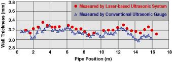 |
| Figure 4 The laser-based ultrasonic system and a conventional transducer-based ultrasonic thickness gauge provide nearly the same measurement results. The small bias toward higher thickness values is associated with the effects of thermal expansion and can be corrected with a small thermal compensation factor. |
Also shown in Figure 4 is wall thickness data that was collected with a hand-held transducer-based ultrasonic thickness gauge after the tube had cooled to room temperature. The laser ultrasonic measurement system accurately captured the wall thickness variations that occurred along the length of the tube. The small bias toward higher thickness values is associated with the effects of thermal expansion.
Laser ultrasonics is not limited to seamless tube and cast-iron pipe applications. It can be used for other continuous manufacturing applications in which real-time data can be used for enhancing processing and improving quality.
Marvin Klein, Ph.D., is president and Tim Bodenhamer is director of marketing and sales for Lasson Technologies Inc., 6059 Bristol Parkway, Culver City, CA 90230, 310-216-4050, fax 310-216-4051, tbodenhamer@lasson.com, www.lasson.com.
Note: 1. C.B. Scruby and L.E. Drain, Laser Ultrasonics: Techniques and Applications (Bristol: Adam Hilgar), 1990.

The Tube and Pipe Journal became the first magazine dedicated to serving the metal tube and pipe industry in 1990. Today, it remains the only North American publication devoted to this industry, and it has become the most trusted source of information for tube and pipe professionals.
start your free subscription
Easily access valuable industry resources now with full access to the digital edition of The Fabricator.

Easily access valuable industry resources now with full access to the digital edition of The Welder.

Easily access valuable industry resources now with full access to the digital edition of The Tube and Pipe Journal.

Easily access valuable industry resources now with full access to the digital edition of The Fabricator en Español.
In this episode of The Fabricator Podcast, Caleb Chamberlain, co-founder and CEO of OSH Cut, discusses his company’s...


