


Contributing Writer
As the name implies, hydroforming is a metal forming process that uses water as a forming medium. In the case of tube hydroforming, a tubular workpiece is placed between two mating die halves. The tube is sealed, normally by metal mandrels inserted under pressure in each end of the tube. Water is introduced through the sealing mandrel, ejecting any trapped air and completely filling the tube. Increasing the water pressure — up to 100,000 pounds per square inch (PSI) — causes the tube wall to conform to the shape of the cavity formed by the mating die halves.
Advantages to hydroforming over a traditional stamping process include weight reduction, improved design flexibility, part consolidation, greater stiffness, reduced joining, elimination of downstream processing, and better dimensional performance.
Weight reduction is paramount in transportation applications such as automotive, railroad, and aerospace, because the weight of the final assembly has a direct impact on subsequent fuel consumption. For situations in which weight reduction is important, substituting lower-density materials for higher-density materials can be advantageous.
The emergence of hydroforming as a viable manufacturing method and the necessity to reduce component weight are driving two distinct transitions. One is the change from traditional stamping to hydroforming, and the other is the substitution of aluminum for steel. The transition from stamping to hydroforming generally has progressed more rapidly than the substitution of aluminum for steel.
However, aluminum sheet is making significant progress in penetrating the stamping market. Examining the introduction of aluminum sheet stamping applications in the automotive industry can be instructive in anticipating developments in aluminum use in hydroforming.
Generally, the need to reduce weight drives aluminum sheet applications. A typical design scenario involves a component that exceeds the maximum weight stipulated by the design criteria. With time running out, the simplest thing to do is to substitute a lighter material. However, this substitution isn't as simple as it sounds.
First, due to differences in forming characteristics, stamping dies for steel and aluminum sheet are not the same. Because stamping tools are expensive, retooling costs can be high.
Second, while the density difference between steel and aluminum suggests a 3-to-1 weight reduction, achieving this is not a realistic expectation. This primarily is due to stiffness or strength differences between aluminum and steel, which drive the need for heavier gauges for equivalent aluminum structures. As a result, weight savings of 25 to 50 percent are typical.
Last, costs must be kept under control. This can prohibit the use of aluminum, which is typically four to five times as expensive as steel.
If the use of aluminum extrusions in the automotive industry follows a path similar to that of aluminum sheet, aluminum's versatility will be another critical factor in its acceptance. Although aluminum stampings might not be dimensionally perfect, they can be fixtured into place and spot-welded for assembly.
A drawback of aluminum extrusions is that they are stiffer and more difficult to correct. Because of this, the dimensional performance of hydroformed aluminum extrusions is much more critical than that of the steel part it replaced.
Three other critical factors that govern aluminum's usefulness are elongation, the variety of alloys and tempers available, and the variety of shapes.
Elongation. A common perception is that aluminum is more formable than steel. However, total elongation, or the amount of stretch before fracture, usually is much greater for steel than it is for aluminum.
The total amount of elongation achieved depends on the steel grade and the aluminum grade and temper, but the maximum normally is 20 percent for aluminum and 50 percent for steel. As a result, greater cross-sectional expansion is a characteristic of steel tubes.
Two other critical factors are uniform elongation, which is the point at which the slope of the stress-strain curve becomes negative (elongation continues with no increase in load), and the n value, which defines the slope of the stress-strain curve after the yield stress.Both of these values also are lower for aluminum than for steel, which makes aluminum forming less stable than steel. As aluminum tube sections expand in the hydroforming process, they are more likely to experience strain localization and premature failure.
Alloys and Tempers. Aluminum comes in a range of alloys and tempers. The best temper for structural design — an application requiring high strength and stability — is T6 (solution heat-treated and artificially aged), while the best temper for formability — an application with low strength and high ductility — is a W (as-quenched) or O (annealed) temper.
T4 (solution heat-treated and naturally aged) is a good intermediate temper for forming, but since the T4 properties vary with time because of natural aging, dimensional variations resulting from springback after forming can cause significant dimensional instability in final parts.
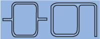 |
| Figure 1: Extruded aluminum allows a variety of geometric features, such as flanges. |
Variety of Shapes. Another driving force of aluminum's growth is the variety of aluminum product shapes. While steel is available only in round cross sections, aluminum is available in round sections and in extruded cross sections of almost any shape.
It can be assumed that initial aluminum hydroforming trials will be done with existing tooling for steel tubes, because of the prohibitive costs of prototype dies. Thus, initial designs and prototypes most likely will concern the viability of hydroforming tubular aluminum products. Subsequent trials might address the technical challenges of hydroforming aluminum shapes.
Extruded aluminum is an attractive product form because of the geometric features that can be included in a part. Figure 1 illustrates generic aluminum cross sections that are possible through extrusion.
These types of cross sections can feature flanges for attachment of subcomponents, variable wall thickness, multiple hollows, and sharp corners for improved stiffness. While these geometric features facilitate more design possibilities, they can cause difficulties for manufacturing using hydroforming.
Prebending — bending the workpiece before placing it between the die halves — is a common requirement in hydroforming operations. Rotary draw bending, which is well-suited for bending round tubes, has limitations when bending shapes. Stretch bending, another common prebending process, also can be used to shape parts for subsequent hydroforming.
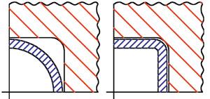 |
| Figure 2: Hydroforming facilitates the formation of sharp-radius corners. |
Generally, rotary draw bending is used for parts with constant-radius bends at discrete distances along the length of the part, whereas stretch bending may be used for parts with continuous, 3-D bends of variable radius. In either case, cross-sectional shape and location of extruded flanges must be considered carefully in the design of the bent shape and in the shape and orientation of the bending dies.
For example, a flange located on the inside diameter (ID) of a bend radius will interfere with the surface of the bend die and may be difficult to accommodate.
Further, the bend contour must permit the straight part to get into the die and the bent part out of the die without interference. This may seem insignificant for those familiar with bending round tube, but it can be a real challenge with an extruded shape.
The die surface should fully support the perimeter of the part at the peak forming pressure of the hydroforming process. For a round tube it is easy to imagine a variety of continuous shapes — oval, rectangular, square, or hexagonal — that could be produced by hydroforming.
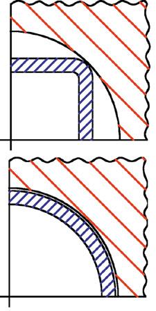 |
| Figure 3: Changing a sharp-radius corner to a more gradual curve is not possible. The inside radius would strain or crack. |
However, unusual cross-section shapes can lead to problems in the hydroforming process. Complicated extruded cross sections will be difficult to form into some other shape through internal pressure.
One major problem has to do with corners. With sufficient internal pressure, a sharp radius can be formed in a hydroformed part, as illustrated in Figure 2. On the other hand, a sharp extruded corner cannot be straightened without inducing very high strains, or cracking, on the inside radius of the corner, as in Figure 3.
As a result, extruded features, such as sharp corners or flange intersections, cannot be altered geometrically by the hydroforming process without inducing a structurally deficient region in the part. The more complex the extruded cross section, the less the section can be changed by hydroforming.
Sealing the tube during the high-pressure forming cycle also can be a challenge. Roll formed and welded steel tubes, because they are formed from rolled sheet, have very consistent wall thickness. Wall thickness of extruded sections can vary by as much as 10 percent, and the profile section dimensions can vary by 0.008 in. per inch of measured dimension.1
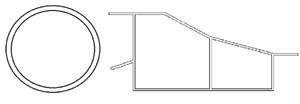 |
| Figure 4: Hydroforming tubular shapes requires that both ends of the tube be sealed before introducing water into the workpiece. Sealing some shapes, such as round (at left), is a routine task. Sealing an irregular component with multiple hollows (right) presents complex technical challenges. |
Because inserting a metal mandrel into the end of the tube is the most common method of sealing tubes, any dimensional variation in a tube can make it difficult to form a good seal.
The presence of sharp corners, flanges, or multiple hollows in the section can present significant sealing issues, as shown in Figure 4. The sealing mandrel for the cross section on the left has a simple round cross section, while the mandrel for the section on the right will be much more difficult to produce.
Finally, cross sections such as those shown on the right in Figure 4 make designing the hydroforming die difficult. Even if this part were straight along the length, it is difficult to imagine upper and lower die halves that could fully support the perimeter of the cross section while still allowing the dies to open and close along a parallel path.
Hydroforming aluminum extrusions involves challenging tool designs, limitations to the degree of shape change possible, and difficulty in sealing the tube at high pressures. Although these are not small challenges, the design flexibility offered by the extrusion process and the potential for weight savings make it difficult to ignore this product form.
1. G. Bartley and B. Evert, "Hydroforming of Aluminum Extrusions for Automotive Applications," Light Metal Age(August 2000).

The Tube and Pipe Journal became the first magazine dedicated to serving the metal tube and pipe industry in 1990. Today, it remains the only North American publication devoted to this industry, and it has become the most trusted source of information for tube and pipe professionals.
start your free subscription
Easily access valuable industry resources now with full access to the digital edition of The Fabricator.

Easily access valuable industry resources now with full access to the digital edition of The Welder.

Easily access valuable industry resources now with full access to the digital edition of The Tube and Pipe Journal.

Easily access valuable industry resources now with full access to the digital edition of The Fabricator en Español.
In this episode of The Fabricator Podcast, Caleb Chamberlain, co-founder and CEO of OSH Cut, discusses his company’s...


