


Contributing Writer
Many articles have been written on the different types of entry end equipment for tube and pipe mills. Most of these articles concentrate on the specific equipment that is used to feed the coils to the mill. This article focuses on the presentation of the strip, including the coil end weld, to the mill.
In a continuous tube producing operation, after the new coil passes through the flattener, it is fed into a coil end welder and a strip accumulator. Within the coil end welder, the new and old coil ends are welded together, usually using either gas tungsten arc welding (GTAW) or gas metal arc welding (GMAW). GTAW is generally employed on small-diameter, light-gauge mills, whereas the GMAW process is used on larger mills.
The GMAW process produces an overthickness at the weld joint because a filler wire is introduced into the welded strip joint. This overthickness can be from 10 to 50 percent of the thickness of the coil ends being joined. About 75 to 80 percent of this overthickness occurs on the top of the weld, and the remainder occurs at the bottom.
Since the top of the weld usually goes into the inside diameter (ID) of the pipe or tube, the overthickness can sometimes cause problems with ID scarfing devices. In addition, the bottom of the weld passes over the roll tooling that is used to form the tube, so the overthickness can harm the finish of the tooling.
To eliminate these potential problems, the excess material at the joint can be removed by the milling process. This process can be done on the top, bottom, or both sides of the weld. Since the milling operation produces a large amount of scrap chips, it is usually done at a station adjacent to the welding area instead of in the same area.
As with welding, the strip must be securely clamped to ensure proper function of the milling unit. Figure 1 shows a typical coil end welder with a milling device next to the weld fixture. If properly adjusted, the milling device removes all the excess weld material so that the welded joint is the same thickness as the prime coil.
For a 6-inch-diameter pipe, the milling operation adds about 45 to 60 seconds to the overall machine cycle time of the shear welder. However, any problems that would be caused by the overthickness are eliminated.
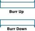 |
| Figure 1: Edges of coils always have a burr up or down condition. |
After the coils are joined, the strip accumulator pulls strip off the uncoiler and refills itself. Although many different types of strip accumulators are available today, this article focuses on horizontal units. First, however, how can the entry twist section, which is required on all horizontal units, be advantageous?
Since most tube and pipe mills process slit coils, the edges of the coils always have a burr up or down condition (see Figure 1). When the strip passes into the mill, this burr should always be in the same relative position.
In the past, this meant that the coils were fed off the uncoiler in alternating fashion—first over payoff, then under payoff. It also meant that the operators had to be very careful to prestage the coils properly in front of the entry section so that burr orientation was not disturbed.
Today, a rotating pinch roll device is available that rotates the loose tail-end strip 180 degrees before the end is welded to the new lead-in strip. This unit is located directly after the shear welder or milling unit.
When one of these devices is used, an over- and under-payoff uncoiling system is unnecessary. Since all coil loading is performed in the same manner with this device, coil loading cycle speed can be increased. The rotating pinch roll does not add any downtime during entry end coil changeover because this operation can occur while the new coil is fed into the shear welder.
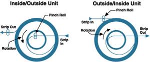 |
| Figure 2: Strip can flow different ways in horizontal accumulators. |
The device that allows the tube mill to run continuously is the strip accumulator. The two basic styles of horizontal units are outside/inside and inside/outside. Figure 2 shows the two different strip flows for these accumulators.
With the outside/inside units, the strip is fed into the accumulator on the outside diameter (OD) and is fed to (actually pulled by) the mill from the ID. This style is often used on smaller low- and high-speed mills.
With the inside/outside units, the flow through the unit is the opposite. The strip is pulled off the uncoiler into the ID of the accumulator, and it exits on the OD. These units are typically used on larger tube mills.
Each type of accumulator functions better on certain mills for several reasons. In the case of the OD/ID units, the inner bundle at the exit of the unit is tightly wound. On fast, light-gauge mills, this is an advantage, since the strip is more easily controlled when it is tightly wrapped.
 |
| Figure 3: A strip storage chart shows the amount of time that can be gained by filling at very high speeds. |
However, this also means that the mill actually needs to supply additional horsepower to remove the strip from the accumulator. This is not a problem on small mills, but it could cause problems on larger mills. To overcome this situation, a pullout pinch roll can be added at the exit of the accumulator.
Another factor that makes OD/ID units more suitable for smaller mills is that on some models, the fill speed is restricted to a certain multiplier (usually about 2.5) of the mill speed. On small mills, this is usually not a problem since the coil length is longer with thinner strip.
On the ID/OD units, there is no relationship between fill speed and mill speed, so the fill/mill ratio can be very high, making it more appropriate for larger tube mills. The coil storage chart in Figure 3 shows the amount of time that can be gained by filling at very high speeds. As shown, the coil length has a dramatic effect on the amount of downtime available for entry end coil changeover.
Probably the least important aspect of a horizontal strip accumulator is the total amount of strip it can store. What is important, though, is the amount of effective or usable storage that the system can provide.
Consider the example of running a product that is .250 inch thick at 100 feet per minute (FPM) with an average coil OD of about 60 inches. This means that the pounds per inch width (PIW) is about 675.
With proper design, almost any horizontal accumulator could easily hold about 2,000 feet of product this size, but the coil in this example is 792 feet long. The chart in Figure 4 shows that the effective or usable storage is only 475 feet if the accumulator is fed at 250 FPM, and 633 feet if it is fed at 500 FPM.
This illustrates two important points. First, it shows that storage is increased by filling at higher speeds. In this case, by filling at 500 FPM, effective storage is increased by about 33 percent over a system that fills at 250 FPM.
This equates to about 1.5 minutes more available downtime during coil changeover, which can be the difference between truly running continuously and occasionally having to stop the mill because the coil changeover takes some extra time.
Second, it shows that, for this example, storage of more than 650 feet in the accumulator has no advantage. It is true that if there is more storage in the unit and the coil changeover is unexpectedly long, the mill can run continuously during this period. For example, if the unit holds 2,000 feet, and 1,500 feet are used during a changeover cycle, the extra storage allows production to continue.
However, what happens when the accumulator is refilled with a 792-foot coil? You cannot put 1,500 feet of strip in the accumulator when the coil used to fill the unit is only 792 feet long. The only way to refill the unit is to stop the mill and refill. Stopping the mill to fill the accumulator defeats the sole purpose of the unit, which is to run continuously.
Today's entry end equipment for tube and pipe mills can provide tube producers with ways to bring continuous operation, increased productivity, and higher quality to their specific applications. By discovering the types of coil equipment best suited to various applications, tube and pipe makers can ensure they have the right solution for their individual needs.

The Tube and Pipe Journal became the first magazine dedicated to serving the metal tube and pipe industry in 1990. Today, it remains the only North American publication devoted to this industry, and it has become the most trusted source of information for tube and pipe professionals.
start your free subscription
Easily access valuable industry resources now with full access to the digital edition of The Fabricator.

Easily access valuable industry resources now with full access to the digital edition of The Welder.

Easily access valuable industry resources now with full access to the digital edition of The Tube and Pipe Journal.

Easily access valuable industry resources now with full access to the digital edition of The Fabricator en Español.
In this episode of The Fabricator Podcast, Caleb Chamberlain, co-founder and CEO of OSH Cut, discusses his company’s...


