


Calculating k-factors for the press brake
The k-factor is important, but it’s one factor among many for machine operators to consider
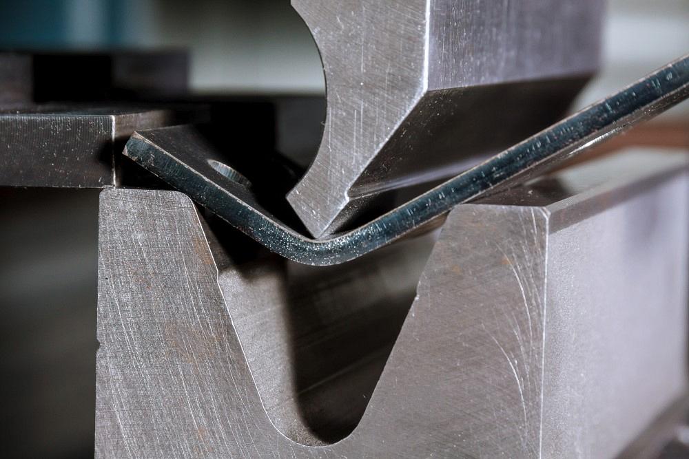
ZhakYaroslavPhoto / iStock / Getty Images Plus
Question: We currently bend A36 material thicknesses from 16 ga. up to 1 in. and, occasionally, various thicknesses of stainless steel and aluminum. We recently added a new press brake and are now faced with the challenge of recalculating our k-factor values and creating new DXF flat patterns of all bent parts.
What is the best way to go about creating data tables with calculated inside radius, k-factors, and all other necessary information we need to correctly design the parts in 3D CAD?
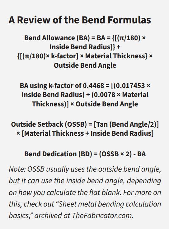
Answer: The answer is not that difficult. You will still use the same formulas as before. Before I delve into the details, though, let me briefly go over the formulas and functions.
We all need to be using the terms and labels with the same meanings. This is especially important when it comes to the k-factor, as many people confuse the k-factor with the bend allowance (BA). In fact, I’ve heard many basic bending terms—the BA, the bend deduction (BD), outside setback (OSSB), and k-factor—used interchangeably. They’re not interchangeable, and using them incorrectly adds a lot of unnecessary confusion to any discussion.
A Review of Basic Terms
The k-factor is simply a multiplier that tells you where the neutral axis of a bend will move after forming. It’s a material-specific factor that accounts for the material’s behavior during bending, and it’s inside our formula to calculate the BA.
When sheet metal bends, it expands on the outside surface of the bend and compresses on the inside surface. The neutral axis is a theoretical place within the sheet metal material thickness that experiences no expansion or compression. It’s essentially the dividing line between expansion forces toward the outside radius and compression forces toward the inside radius (see Figures 1 and 2). Because the neutral axis remains the same length as it moves inward, the metal elongates, which we need to accommodate for using our bend calculations.
Note that the neutral axis can never exceed 50% of the material thickness (with a k-factor of 0.50). If you’re forming a wide radius, you might calculate a k-factor greater than 50%, but if that’s the case, you must return that value to 0.50. Why? Because the compression area within the bend cannot exceed the expansion area.
Bending a Test Piece
Reverse engineering the k-factor is the only way to determine its actual value, or at least one as close to perfect as possible. You can do this by running test bends, measuring the results, and extracting the k-factor from the BA formula that incorporates the results you measured. It might be your best option, especially if you’re creating a table.
But—and this is a big but—you also need to consider the material tolerances, including tensile, yield, and thickness. You could end up with some very precise k-factor data from a test piece, but the test piece material might not match the properties of the material you bend in production. Regardless, if you have just found the BA by bending test pieces, you might not need the k-factor anyway.
Calculating the K-Factor, No Test Piece Required
There is another way to calculate the k-factor without bending any test pieces. It’s not perfect, but then again, neither is bending a test piece. Not only can material properties change, but so can the exact properties of the tooling you use (differing amounts of friction) and different methods of forming.
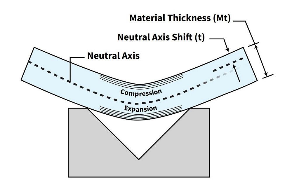
FIGURE 1. The k-factor, expressed as t/Mt, is a ratio that describes the neutral axis’s shift inward during bending.
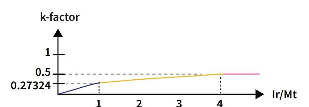
With all that said, you can start by graphing the k-factor, as shown in Figure 3. This shows the maximum value for the k-factor at 50% of the material thickness, noted by the red line. Where the yellow and red lines meet (point 4 in the chart) represents an inside bend radius equal to four times the material thickness. Above that, you will calculate factors larger than 50%, but you shouldn’t use them. As the chart shows, you need to maintain your k-factor at that maximum 0.50 value.
Location 1 on the chart, where the blue and yellow lines meet, is the k-factor value for a sharp or minimum producible inside radius for an air form. Any value below this puts the bend into an area that exceeds the physical limits of compressibility—at least for our baseline, mild steel material. As I have stated many times before, sharp bends are the bane of air forming accuracy.
The minimum k-factor for air forming can be expressed as (4-π)/π, or 0.27324. We subtract that value from our maximum k-factor value of 0.5:
0.5 - 0.27324 = 0.22676
This result gives us our range of possible k-factors as noted on the yellow line on the chart. Next, we divide 0.22676 by 3:
0.2267/3 = 0.07558
This gives us our multiplier—that is, the number we multiply to our bend’s inside radius-to-material thickness ratio. We find that ratio by dividing the inside bend radius by material thickness. I’ll use a 0.093-in. inside bend radius in 0.062-in.-thick material.
0.093/0.062 = 1.5
We then multiply by our multiplier, 0.07558, and add the result to the minimum k-factor of 0.273:
0.07558 × 1.5 = 0.113
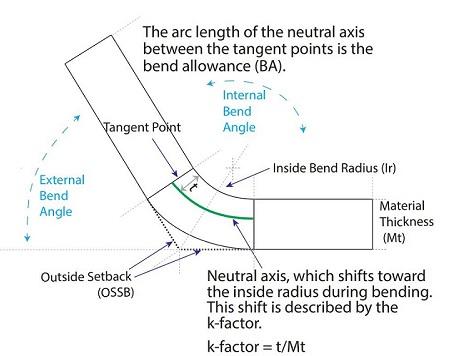
FIGURE 2. The k-factor describes the neutral axis’s shift inward during bending. That shift causes the metal to elongate, which we accommodate for in our bend calculations.
0.113 + 0.273 = 0.386
That makes our k-factor 0.386. All this can be summed up in the following formula. Again, you derive the minimum k-factor and multiplier from the chart in Figure 2.
K-factor= [Multiplier × (Inside Radius/Material Thickness)] + Minimum K-factor
Breaking Down the Bend Allowance
You’ve found the k-factor. Now what? What do we do with that number? How is it applied, and why should you care? Why you should care depends on the quality of the product you want to produce. Understanding the k-factor makes a big difference. First, look at your BA formula:
BA = [(0.017453 × Inside Bend Radius) + (0.0078 × Material Thickness)] × Outside Bend Angle
In this equation, 0.017453 is π/180, which converts degrees into radians, or units of measure for angles based on a circle’s radius. We perform this conversion because trigonometric functions in mathematical calculations typically require angles to be in radians rather than degrees. When you multiply the converted angle (in radians) by the radius, you’re essentially calculating the length along the arc of the circle formed by the bend. So, π/180 multiplied by the inside radius represents the arc length along the neutral axis for one degree of angle.
The second part of the equation again begins with the conversion of degrees to radians (π/180), which is then multiplied by a k-factor of 0.4468, giving us the 0.0078 figure in the formula. That represents the compensation that occurs when the neutral axis shifts inward during bending, causing material to elongate and adding length to the part dimensions.
We now know the total length of the arc and the extra length created by the neutral axis shift. Still, until now, we’ve just calculated for one degree of bend angle. Now, we multiply the total external bend angle, as measured from outside of the bend. (Note: Never use the inside bend angle when calculating the BA.)
One Factor Among Many
Note that plenty of variables can mess with your k-factor values, especially if operators choose different die openings or use different methods of forming. So, what is the “best” way to recalculate your k-factor tables? Perhaps it’s an Excel spreadsheet. Perhaps you can bend test pieces. Just know that the k-factor is but one variable among many to consider.
About the Author

About the Publication

subscribe now

The Fabricator is North America's leading magazine for the metal forming and fabricating industry. The magazine delivers the news, technical articles, and case histories that enable fabricators to do their jobs more efficiently. The Fabricator has served the industry since 1970.
start your free subscription- Stay connected from anywhere

Easily access valuable industry resources now with full access to the digital edition of The Fabricator.

Easily access valuable industry resources now with full access to the digital edition of The Welder.

Easily access valuable industry resources now with full access to the digital edition of The Tube and Pipe Journal.

Easily access valuable industry resources now with full access to the digital edition of The Fabricator en Español.
- Podcasting

In this episode of The Fabricator Podcast, Caleb Chamberlain, co-founder and CEO of OSH Cut, discusses his company’s...
- Trending Articles
1
Tips for creating sheet metal tubes with perforations

2
Are two heads better than one in fiber laser cutting?

3
Supporting the metal fabricating industry through FMA

4
JM Steel triples capacity for solar energy projects at Pennsylvania facility

5
Omco Solar opens second Alabama manufacturing facility
