


Press brake controllers and the bend deduction of sheet metal
Factors that influence the accuracy of bend calculations on a press brake
romaset / iStock / Getty Images Plus
Question: I currently use a press brake that works out the flat length of material before it is bent, but it seems not to obey any of the bend allowance formulas I have seen anywhere.
For example, I typically bend 0.67-mm-thick sheets with a 12-mm die and a 1-mm-radius punch. For a 90-degree bend, the machine calculates that I need to take 1.54 mm from the original material, given the fact it’s dimensioned on the outside. Given our tooling, we should achieve an inside radius of 1.872 mm. But when I plug this into our bend formulas, the resulting bend deduction comes out nowhere close to the 1.54 mm that the machine says.
It would be great if you could give me some pointers as to why the machine seems to be programmed with a different formula than all the ones I read about. Also, sorry about the metric measurements; I am from the U.K.
Answer: Not to worry about the metric measurements; we work both in metric and imperial units here in the states too. That being said, let’s see if we can solve the issue at hand.
First, a disclaimer: Without actually being there and working with your press brake and its controller, it is hard to confidently say why you are finding what you are finding. Also, because I do not know your target inside bend radius, I will assume it’s 1.0 mm (0.039 in.). I’ll also assume your bend angle is 90 degrees and that you’re air forming using precision-ground tooling.
So, why does your machine seem to use a different formula than the ones you read about? While many press brake controllers use algorithms that vary slightly, they do not vary much from what I am about to describe. In the U.S., these formulas can also be found in Machinery’s Handbook.
There is common confusion about the terms and their application, along with related tool selection issues that should be addressed. These issues bring us back to your question about the data from the press brake controller.
Most controllers make their calculations based on some basic parameters, such as choosing a tool correctly. Modern controllers generally base the calculations using air forming as the method, so if you’re bottom bending, the returned values will be off.
The programs also do not consider the issues caused by using too large or too small of a die opening, or if you’re using too sharp of a punch nose radius. There is also the possibility that the information produced by the controller is misused; for example, is the bend allowance being used where the bend deduction value should have been?
Bend Functions and Their Applications
We’ll start by defining the formulas for the three main bend functions and applications (see Figure 1): outside setback (OSSB), bend allowance (BA), and bend deduction (BD).
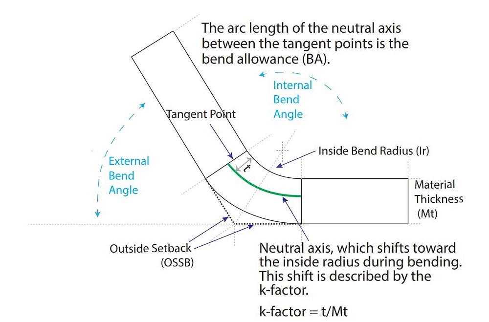
FIGURE 1. The bend allowance, shown here, differs from the bend deduction (BD), which is subtracted (“deducted”) from the total outside dimensions to develop the flat blank. The outside setback, also shown here, is measured from the tangent point to the apex of the bend.
The BA is a value added to the dimensions of the bend from the edge of the part to the tangent point between the flat and the radius. It’s calculated as follows:
BA = [(0.017453 × Inside bend radius) + (0.0078 × Material thickness)] × External angle of bend
Note that the 0.017453 value is pi over 180. That 0.0078 value is found by multiplying 0.017453 (again, pi over 180) by the k-factor. In this case, the k-factor is equal to 0.4468. Also, the bend angle is always given as the outside angle measurement (that is, the external bend angle in Figure 1).
In your application, the BA using imperial measurements would be:
[(0.017453 × 0.039) + (0.0078 × 0.026)] × 90 = 0.0795 in.
Here’s the same formula using metric measurements:
[(0.017453 × 1.0) + (0.0078 × 0.67)] × 90 = 2.0411 mm
Please note that when we compare metric to inch values, the calculations are only slightly different:
0.0795 in. = 1.981 mm
2.0411 mm = 0.080 in.
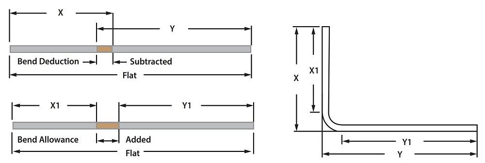
FIGURE 2. The bend allowance is added to the total inside dimension, as measured to the tangent of the bend (X1 and Y1), while the bend deduction is subtracted from the sum of the outside dimensions (X and Y).
The outside setback (OSSB) is a measured distance from the radius and flat tangent point to the apex of the bend:
OSSB = [Tan (Half the bend angle) × (Material thickness + Inside bend radius)
So, for your application, we’d calculate the OSSB as follows:
OSSB in inches = [Tan(45)] × (0.026 + 0.039) = 0.065 in.
OSSB in millimeters = [Tan(45)] × (1.00 + 0.67) = 1.67 mm
Finally, you’d calculate the BD as follows:
BD = (2 × OSSB) - BA
BD in inches = (2 × 0.065) - 0.0795 = 0.051 in.
BD in millimeters = (2 × 1.67) - 2.041 = 1.299 mm
Common Mistakes
Now that we have defined the formulas and calculated some data, let’s apply the information to the flat blank. Figure 2 shows the differences between the BA and BD. We add the BA to the total of the flat lengths, from the edge to the tangent point of the bend radius; in the figure, that’s X1 + Y1 + BA. Conversely, we subtract the BD from the total of the outside dimensions, from the edge to the outside of the bend. In the figure, that’s (X + Y) - BD.
If engineering or design makes the simple mistake of subtracting the BA when it should have been added, then the flat will be wrong. Another common mistake is using the wrong bending method in the calculations. For instance, if you’re bottom bending, you’re stamping the punch nose radius into the material. If you’re air forming, the radius forms as a percentage of the die opening. If you have the wrong forming method, you’ll run the bend calculations with the wrong radius, which in turn throws off everything else.
If you are a regular reader of my column, you should know the importance of the inside bend radius. It’s the heart of bending sheet metal. If we get that wrong, almost nothing will work out. So, if the numbers aren’t working out, check the inside bend radius. How are you confirming that it is correct? Are you using radius gauges or pin gauges? Or, for that matter, is one tool better than the other?
Using radius gauges is fine when you are bottom bending. The punch nose radii come in standard metric and imperial sizes. And, because you are bottoming, the radius on the punch is stamped into the material.
If you are air forming, again, the inside bend radius is floated as a percentage of the die opening. This means that your inside radius will vary from the standard tool increments; the resulting radius rarely lands upon common fixed-tool values, making radius gauges impractical. This is where shop or quality-control pin gauges come into play. Because the pin gauges come in 1-mm or 0.001-in. increments, any inside radius can be checked precisely regardless of the forming method.
Causes of Variation
Reviewing your data, I have to wonder why you are using such a large die opening for such thin material. If you are air forming, which I assume you are, then your inside bend radius is developed as a percentage of the die opening.
For example, an A36 steel with an ultimate tensile strength of 60,000 PSI should produce an inside bend radius that’s about 16% of the die opening. So, for the 12 mm (0.472 in.) die opening, the inside bend radius should be 1.92 mm (0.075 in.)—and 1.92 mm is very close to the 1.872 mm (0.073 in.) that you calculated.
Your machine’s calculation of 1.54 mm (0.060 in.) is the correct BD for an inside bend radius of 1.803 mm (0.071 in.)—close to the 1.872 mm radius you calculated, but not an exact match. Why? Sure, there are possible slight variations in the equations, like a variation of k-factors, which there are valid reasons for doing.
But if the resulting bend radius differs from what you or the machine calculated, material variation might be the cause. As I have discussed many times before, no two pieces of material are the same, even though they might be designated as being the same material grade, thickness, yield and tensile strength, and even formed along the same grain direction.
Material variation also can have an effect on the 20% rule. Named after the air-forming characteristics of stainless steel, the 20% rule is where that 16% value comes from. That said, the rule isn’t exact but instead has a range of values we could have used. The A36 material I chose for this example has values ranging from 15% to 17% of the die opening. That, again, comes from the differences in the material being formed. On occasion, the spread of values could be even greater. Nonetheless, the median value normally is very accurate.
A Start Toward a Solution
Again, without actually being there and working with your press brake and its controller, it’s hard to give you a precise answer as to why your controller does what it does. Regardless, I hope to have offered up some basic background information, shown you how to apply it, given you some ideas about why you are seeing the results you are seeing, and what you might be able to do to correct it.
Remember, anytime you can’t figure out a problem, keep trying; you’ll figure it out. Problems like these can turn into great learning experiences.
About the Author

About the Publication

subscribe now

The Fabricator is North America's leading magazine for the metal forming and fabricating industry. The magazine delivers the news, technical articles, and case histories that enable fabricators to do their jobs more efficiently. The Fabricator has served the industry since 1970.
start your free subscription- Stay connected from anywhere

Easily access valuable industry resources now with full access to the digital edition of The Fabricator.

Easily access valuable industry resources now with full access to the digital edition of The Welder.

Easily access valuable industry resources now with full access to the digital edition of The Tube and Pipe Journal.

Easily access valuable industry resources now with full access to the digital edition of The Fabricator en Español.
- Podcasting

In this episode of The Fabricator Podcast, Caleb Chamberlain, co-founder and CEO of OSH Cut, discusses his company’s...
- Trending Articles
1
Tips for creating sheet metal tubes with perforations

2
Are two heads better than one in fiber laser cutting?

3
Supporting the metal fabricating industry through FMA

4
JM Steel triples capacity for solar energy projects at Pennsylvania facility

5
Omco Solar opens second Alabama manufacturing facility
