


Graduate Research Associate
Edge fracture is a common problem when forming sheets of advanced high-strength steel (AHSS). Several methods are available to test for edge stretchability in these materials.
One of the most popular tests for edge stretchability is the hole expansion test (HET), outlined in the ISO 16630 standard. During a HET, a 10-millimeter-diameter hole is pierced and later expanded using a conical punch. The ratio between the hole diameter when edge fracture occurs and the initial hole diameter, the hole expansion ratio, is used as a metric of edge stretchability. However, some researchers have pointed out that the use of this standard leads to significant scatter in the results, especially among laboratories testing the same materials.
The collar forming test and variations of the initial pierced hole diameter have been used as an alternative to the HET. However, maintaining a uniform cutting clearance along the perimeter is a tremendous challenge in any piercing operation, so results from these tests should be used carefully.
In other testing methods, such as the edge fracture tensile test and half dome test (HDT), the cutting of the tested edge occurs in a straight line rather than in a close profile, which makes it easier to maintain a uniform cutting clearance. But these tests have their own drawbacks such as necking and friction between the blank and tool, respectively. (See “Blanking and edge fracture in flanging of AHSS, Part I,” November/December 2017 STAMPING Journal.)
Another edge stretchability test using straight cut edges, the double bending test (DBT), was reported by ArcelorMittal France in 2010. The metal is bent two times to achieve the desired results (see Figure 1). In the first step, a rectangular sample is prepared using the desired cutting clearance. Later, a 90-degree bending operation is performed parallel to one of the cut edges. The height of the flange created in this operation should not be excessive to prevent buckling issues during the second bending operation. Finally, the second bending operation is performed perpendicular to the first bending.
This type of deformation creates tensile stresses along the cut edge, leading to edge fracture. The bending stroke, the thinning at the edge, or the major strains at the onset of fracture can be used to compare the edge stretchability of different materials or to establish the optimum cutting technique/clearance for the analyzed material.
According to Bouaziz et al. (2010), the preparations required for this test seem to be relatively simple, and no necking is observed before the edge fracture. Also, the effect of burr orientation (for instance, burr-up, as required in the ISO 16630 standard) does not affect the results of the test. Nevertheless, buckling issues during testing may be observed on the sample.
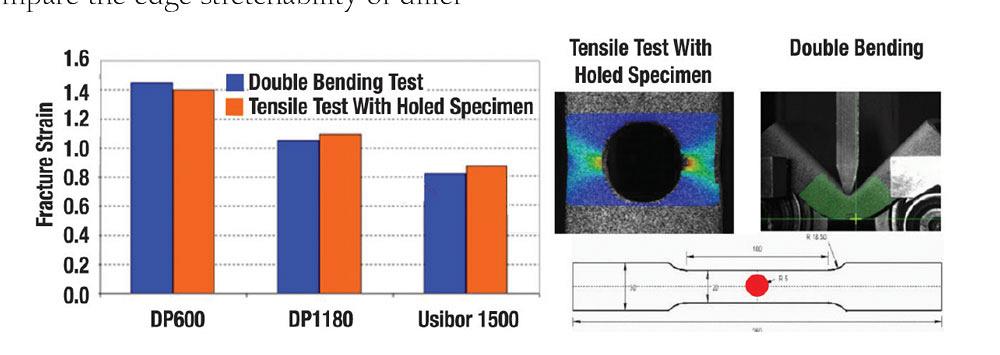
Additional studies reported in 2017 by ArcelorMittal France indicated that effective strains at fracture for DBTs are in agreement with those obtained from tensile tests using holed specimens. This observation (see Figure 2) was made for DP600, DP1180, and Usibor1500 materials. The effective strains at fracture were calculated considering the ratio between the initial thickness and the thickness at fracture and assuming an isotropic material behavior.
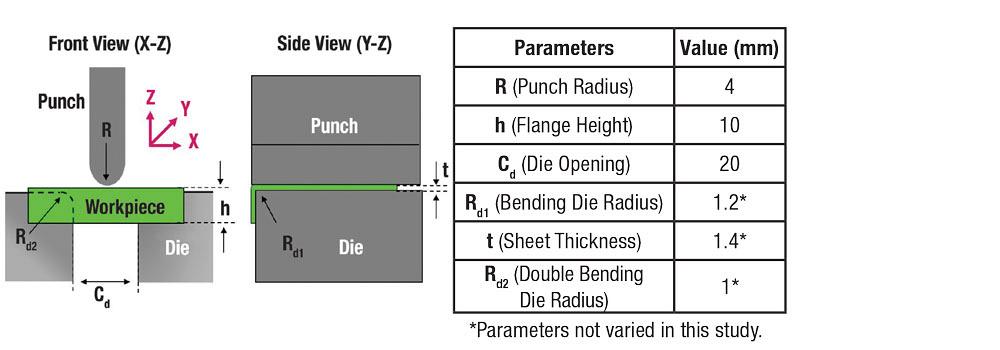
Because ArcelorMittal has not described the tool geometry and experimental setup, researchers at The Ohio State University’s Center for Precision Forming have conducted finite element (FE) simulations to determine an adequate sample size and tooling configuration for the DBT. Using 1.4-mm TRIP780 material as an initial example, the researchers investigated the effect of the punch radius (R), flange height, and die opening. The initial geometric parameters used in the simulations are represented and listed in Figure 3; the sample size was 80 mm long (X direction) and 50 mm wide (Y direction).
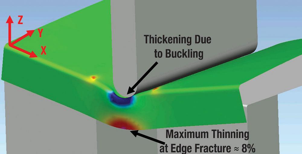
The researchers conducted the FE simulations using PAM-STAMP software. They used maximum thinning of 8 percent at the edge as the fracture criterion; they used HDTs to measure this value, and it is in agreement with values reported by other researchers for TRIP780. Figure 4 shows an example of a thinning calculation for the conditions described in Figure 3. The red area indicates the higher thinning along the edge, which is under tension.
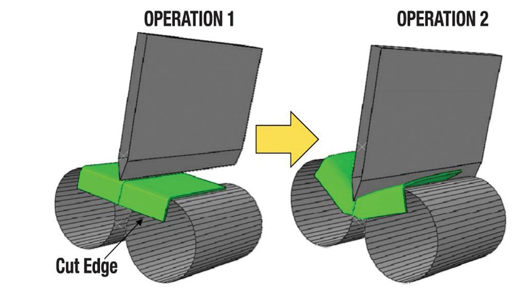
Figure 1
In the double bending test, an initial flange, parallel to the cut edge, is created in operation 1. A perpendicular bend is made in operation 2, leading to edge fracture (Bouaziz et al., 2010).
A punch radius of R = 6 mm resulted in a 30 percent increase of buckling on the sample when compared to the original R = 4 mm, while the location of maximum thinning shifted from the edge to the punch/sample contact point when using R = 2 mm. Thus, R = 4 mm is the proposed value for future studies.
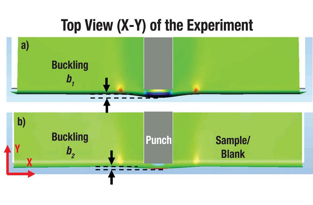
As expected, when the flange height was reduced from 10 mm to 7 mm and 4 mm, the buckling observed on the sample reduced by up to 50 percent (see Figure 5).
Researchers adjusted the die opening between 12 and 24 mm in increments of 4 mm. The peak load calculated for each case increased as the die opening decreased. A load three times larger was calculated when the die opening was reduced 50 percent, from 24 to 12 mm.
For testing a 1.4-mm-thick metal, a punch radius of R = 4 mm, flange height between 4 and 7 mm, and a die opening of 20 mm are the values recommended based on the current simulation results. Nevertheless, the aforementioned effects correspond to individual variations of the parameters, and the CPF researchers are making additional efforts to consider possible combined effects. Experiments using the DBT to estimate strains at edge fracture for different AHSS are part of the future work of this project.
ReferencesO. Bouaziz, S. Douchamps, L. Durrenberger, and A. Bui-Van, “The double bending test: a promising new way for an optimal characterization of cut-edges ductility,” from IDDRG 2010, sponsored by International Deep-Drawing Research Group, Graz, Austria, 2010. P. Dietsch, K. Tihay, A. Bui-Van, and D. Cornette, “Methodology to assess fracture during crash simulation: fracture strain criteria and their calibration,” Metallurgical Research & Technology, Vol. 114, No. 6 (2017), p. 607.
Professor Emeritus and Director - Center for Precision Forming


The Fabricator is North America's leading magazine for the metal forming and fabricating industry. The magazine delivers the news, technical articles, and case histories that enable fabricators to do their jobs more efficiently. The Fabricator has served the industry since 1970.
start your free subscription
Easily access valuable industry resources now with full access to the digital edition of The Fabricator.

Easily access valuable industry resources now with full access to the digital edition of The Welder.

Easily access valuable industry resources now with full access to the digital edition of The Tube and Pipe Journal.

Easily access valuable industry resources now with full access to the digital edition of The Fabricator en Español.
In this episode of The Fabricator Podcast, Caleb Chamberlain, co-founder and CEO of OSH Cut, discusses his company’s...


