


Why the right tooling matters for an old press brake
Getting tooling in order will make the process of bending metal easier
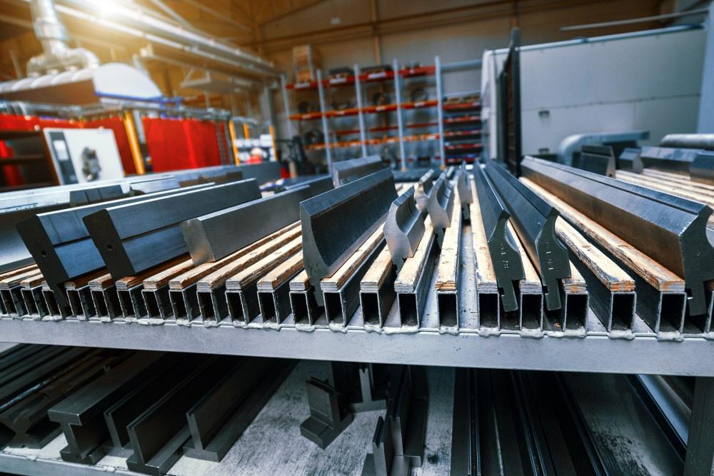
If your shop is having trouble setting up an old press brake, you might want take a look at your tooling. Getty Images
Question: I'm a toolmaker now working at a new company in the model shop, mostly doing prototypes. We also do a fair amount of simple sheet metal parts, boxes, and hat sections for electronics test tools. The sheet metal guy they had retired before I came in, and the other two gentlemen don’t, or won’t, touch sheet metal.
I’ve assumed the role of the sheet metal guy. We have a 1970s vintage Di-Acro 4-ft. brake and a mid-90s 8-ft. Piranha with a CNC retrofit. All of the tooling is just as old.
What is killing me is setup time. Every time I have to change tools, I have to square up the backgauge. How did guys do this back in the day? I have tried using 123 blocks; dial indicators; and even letting the bottom die float and bottoming the punch, then snugging up the die.
The parts we make on the brake don’t have tight tolerances, and usually I can meet the requirements, but sometimes it can take half a day just to set up a single tool. It is fun and gets me away from the milling machine, but I would always like to get better.
Answer: The way you describe your question, I’m going to assume that you are using traditional, and probably worn-out, planer-style press brake tooling. While worn-out tooling is an issue unto itself, incorrect use of the planer tooling is at the heart of your setup issues. Let me explain.
Planer Versus Precision-ground Tooling
Both precision-ground and traditional planer press brake tooling have their place in the industry. However, the way they are manufactured and how they are used are quite different.
Planer press brake tooling is produced on a planer in lengths of up to 40 ft. The die stock is loaded into the planer and referenced from an X-Y axis coordinate. The press brake tooling is then cut to profile from that X-Y axis.Precision-ground tooling starts with the die stock. Lengths of approximately 32 in. (and no longer) are loaded into the tool grinder and ground from the outside surfaces of the tool blank toward the tool center to produce the appropriate profile.
Precision-ground press brake tools are ground on all surfaces toward the center, and the tool tolerances are held to within a few 10 thousandths of an inch. This means you can place these tools into the press brake facing different directions, even within a single toolholder, while still holding a standard height and a common tool center. These tools are so precisely built that you can even mix and match tooling from different manufacturers.
Compare that to the tools that are produced on a planer. When these tools are made, the die or punch stock is referenced from a single X-Y corner on the bed of the planer. From there the planer cuts the tool to profile in lengths up to 40 ft., holding a part tolerance of ±0.005 in. over 10 ft.—which, I might add, is very high quality for the process. It also attests to the craftsmanship of the machine operator. Nonetheless, that X-Y reference corner and the ±0.005-in. error over 10 ft. are the root cause of many issues you are dealing with, and here is why.
The Root Causes of Setup Issues
Let’s start by looking at the ±0.005 in. over 10 ft. of variation down the tool’s length. To find out why this variation matters, we need to look at how these tools are going to be used.
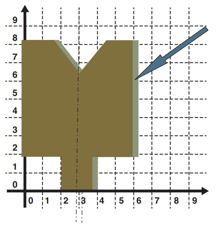
FIGURE 1. When one tool is front-facing and an adjacent tool has its back facing forward, you increase the error between the two mating tools.
Traditional planer tools usually come in longer lengths—10, 16, 20 ft. or more. Then it is up to you to cut them to the working length you require for the project. When you cut it, you need to make sure you mark them so you can orient the cut tools in the same direction, front to back.
This matters because the tool that you are cutting was manufactured from a single X-Y coordinate. When you place the tooling into the press brake, the tooling must be kept facing the same direction, front to back. And when you are remating, two sections of tooling must be reassembled with the original tool section it was cut from.
This goes back to the ±0.005 tolerance error in the tool. Let’s look at a worst-case scenario, considering the error of ±0.005 over every 10 ft. of planer tooling. Over 40 ft., you multiply 0.005 by 4 to get 0.020 in. If you try to mate two tool sections that came from opposite ends of the entire tool length at the time of manufacture, the total error in the two pieces of tooling will not allow them to align correctly.
Only three or four thousandths of an inch difference can manifest as several degrees of bend angle variation between two different, unaligned (centered) punches and dies. True, you often cannot see it; nevertheless, that difference is there, and you will fight it.
Now try to picture this: You have a misaligned die on the bottom, and in the punch you have the same amount of error but aligned differently front to back. When this happens, you increase an already present amount of difference, and your bend angles are all over the map.
Moreover, centering the punch into the die becomes completely impossible. Because you are using tools planed from an X-Y coordinate, what happens if you have one tool reversed in relation to the other? That is, one is front-facing and the mating tool has its back facing forward? You again increase the error between the two mating tools (see Figure 1).
Also, don’t forget about residual stress. Because planer tools come in long lengths, you’ll need to cut them to size. Every time you cut the tool, you will be releasing any residual stress still present in the tool, be it a punch or die. While seldom dramatic, the residual stress releases small amounts of bow, twist, and camber. This compounds all of the tooling issues we have just been discussing. This knowledge also will help you “make the case” for applying the solutions you are about to learn regarding your shop practices and machine setup.
The Solution
When cutting a new tool, mark each cut 1-1, 2-2, 3-3, etc. (see Figure 2), and only on one side. That way, you can not only remate tooling at the cut but also keep all of the tool sections facing the same way, front or back. If you set up a job and see the reference points move to the other side of the tool relative to the other (that is, 1 is in front on one tool segment and in back on another tool segment), you’re only adding more error into your setup.
Older tooling like yours was likely cut to length years ago. If that’s the case, you will need to sort through your tooling and try to put them back into sets, order of cuts, and direction (front and back). Trust me, it’s not going to be easy. You can compare manufacturing markings, breakaway cuts, and tool heights and widths. Do your best, and then mark the tools for future use. It won’t be perfect, but you will make setup easier and improve your finished products.
Centering Your Tooling
Now that you have your tools sorted, marked, and ready to load into the brake, you need to remember that no two planed toolsets are the same. This means that the location of the punch and die centers will change.

FIGURE 2. When cutting planer tooling, mark cuts as shown here, and only on one side. This allows the tooling to be remated for alignment purposes and centering.
You’ll need to calibrate the backgauge to the center of the new punch (the center of the bend) using a gauge block. Program the brake, fine-tune the program, and you’re off to the races.
Precision-ground Tool Lengths
If you’re looking to upgrade or purchase more precision-ground tooling, know that such tools come in lengths up to about 3 ft. If you’re looking at what you think is precision-ground tooling because of the tool profile, but it comes in lengths of 8 or 10 ft. or longer, it is not a precision-ground tool; it is a planer tool. If you purchase one of these, you will have the same issues with setups we have been discussing, even if you are putting that tool in a state-of-the-art press brake. Just because it looks like a precision-ground tool doesn’t make it one; the “tell” is the tool length.
A Better Day at the Brake
I feel your pain of fighting setups with this type of tooling. I fought many setups and press brakes before I learned about planer press brake tooling and how many of my issues were directly related to what I didn’t know.
Take the time to get your tools in order and think about how to apply what you now know. If you do this, I am optimistic your setups will be easier to perform, the parts you are producing will be better and more consistent, and you will have a better day at the press brake.
Event: Precision Press Brake Virtual Certificate Course
This is a fully virtual class will run Feb 7-9. Includes 3 sessions (10+ hours) of live instruction, resource materials, and 3 hours of on-demand videos to enhance your learning experience. Live sessions run from Noon to 3:30 p.m. Central Time each day. Plus, receive your own copy of Steve’s textbook, Bending Basics ($95 value). At the end of the course, you’ll have the opportunity to earn FMA’s Precision Press Brake certificate by successfully completing an online exam.
With 40+ years of experience in the sheet metal industry, instructor Steve Benson will help press brake operators, engineers, and other related personnel to improve their design, communication, and execution of press brake configurations. At the end of the course, you’ll have the opportunity to earn FMA’s Precision Press Brake certificate by successfully completing an exam.
About the Author

About the Publication

subscribe now

The Fabricator is North America's leading magazine for the metal forming and fabricating industry. The magazine delivers the news, technical articles, and case histories that enable fabricators to do their jobs more efficiently. The Fabricator has served the industry since 1970.
start your free subscription- Stay connected from anywhere

Easily access valuable industry resources now with full access to the digital edition of The Fabricator.

Easily access valuable industry resources now with full access to the digital edition of The Welder.

Easily access valuable industry resources now with full access to the digital edition of The Tube and Pipe Journal.

Easily access valuable industry resources now with full access to the digital edition of The Fabricator en Español.
- Podcasting

In this episode of The Fabricator Podcast, Caleb Chamberlain, co-founder and CEO of OSH Cut, discusses his company’s...
- Trending Articles
1
Tips for creating sheet metal tubes with perforations

2
Supporting the metal fabricating industry through FMA

3
JM Steel triples capacity for solar energy projects at Pennsylvania facility

4
Are two heads better than one in fiber laser cutting?

5
Fabricating favorite childhood memories
