


Contributing Writer
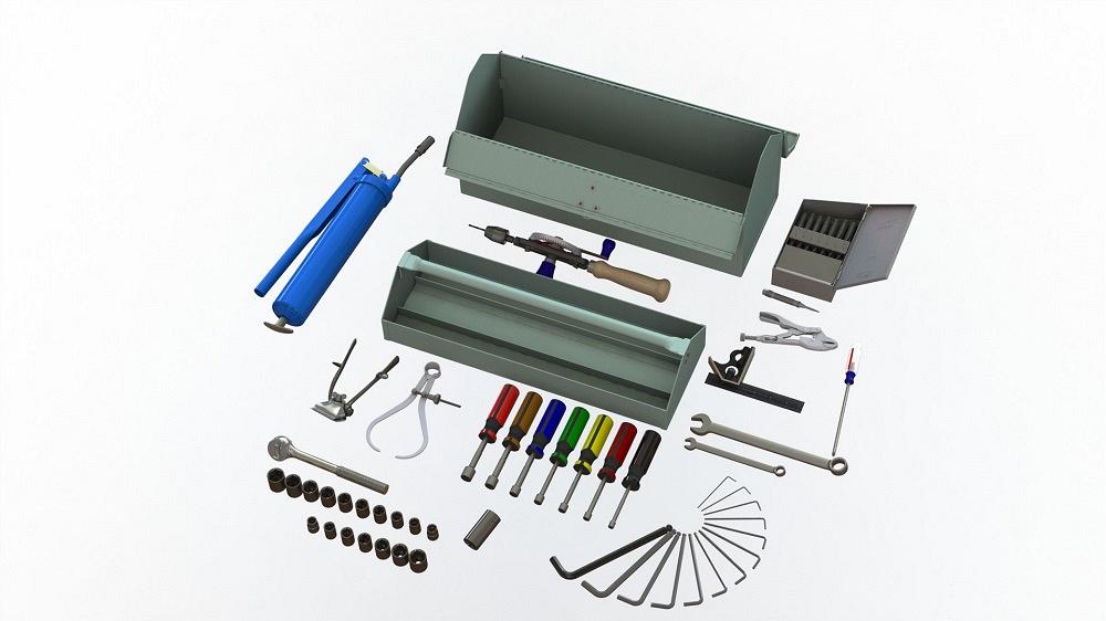
FIGURE 1. Props help to convey the use and scale of a design. For example, this tote box for hand tools was created for a prop discussion in 2020.
When presenting and reviewing a design, props are often used to convey scale, operation, and feel. We introduced a tote box design using such props (hand tools) in August 2020 (see Figure 1).
To avoid excess labor on the part of the CAD jockey, such visual actors are often downloaded from sources such as mcmaster.com, 3dcontentcentral.com, and grabcad.com. The author is familiar with these resources and values them greatly.
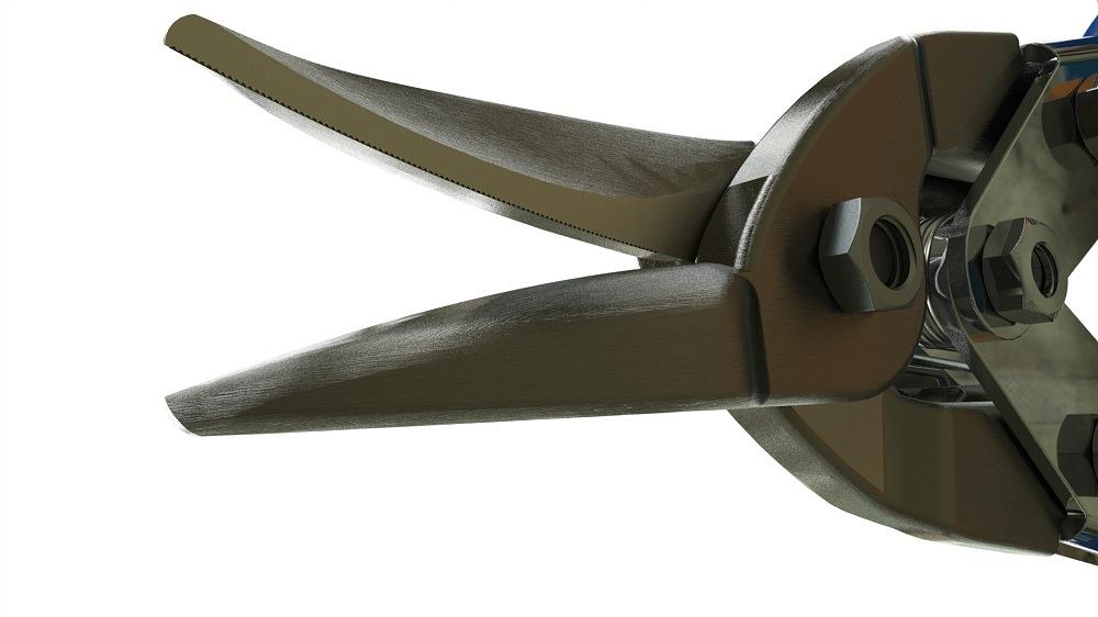
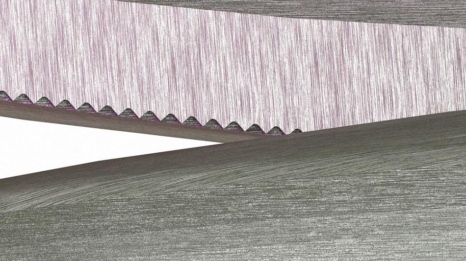
The model for aviation tin snips shown in Figure 2A was provided by Mark Gunn. He posted it way back in 2014 on grabcad.com. The 3D model is a faithful representation of an actual tool. Figure 2B shows the curved shape of the jaws. The same sldprt is used for both jaws, just as an actual product might.
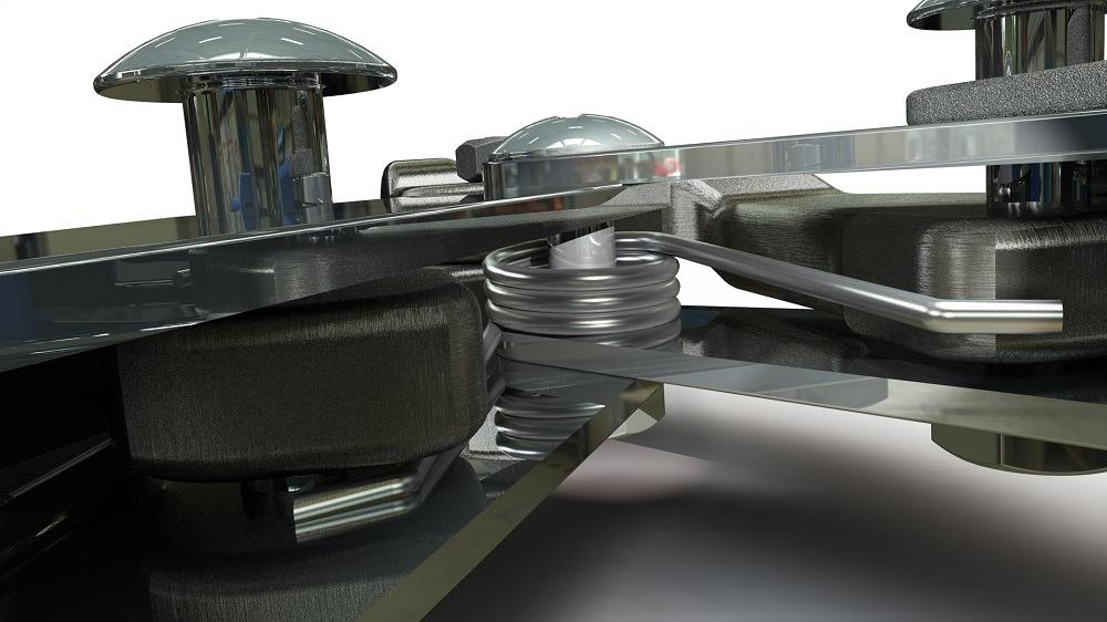
Figure 2C is a close-up of the serrated cutting edge. Gunn made the effort to add nearly complete detail to the model—not just with the jaws and handles, but with the torque spring as well. The spring appears in Figure 2D.
Gunn’s tin snip model could be downloaded as a STEP file and imported as a dumb model into SolidWorks or other brands of 3D CAD. Textures and kinematics would be lost. Thus, here’s the part of the pitch for native CAD files.
The imported STEP might serve immediately as a prop, albeit gray and stiff. With just a little extra work, textures (see Figure 2C) and kinematics could be added to the import. In contrast to importing STEP or IGS files, downloading the native CAD is sometimes advantageous.
Gunn’s tin snips are lovely, and as inspiration for this article, grabcad.com doesn’t mind offering native CAD files for any (old or new) version. In contrast, some other download libraries restrict the downloads to current versions of the CAD.
Gunn’s aviation tin snip model, when opened in the SolidWorks, arrives with its components mated. These mates allow a mouse-drag to open the lock and operate the jaw mechanism—full kinematic motion. As a prop model being used to illustrate a design, realistic posing is part of its charm.
Perhaps as a study in overmolded plastic or as an example of a levered hand tool mechanism, this downloaded model has other uses to the designer-jockey. As a CAD jockey, the model is useful as a training exercise: It demonstrates several efficient modeling techniques.
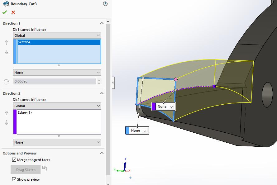
In Figure 3, we see Gunn’s use of the Boundary-Cut tool. Similar to a Swept-Cut, the Boundary-Cut uses a profile sketch and a path. In this example, an available edge is used as the path. The profile has the curve that defines the outside of the jaw.
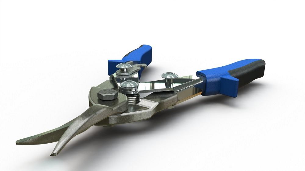
FIGURE 2A. Fellow CAD jockey Mark Gunn posted this model for aviation tin snips on grabcad.com. It is very realistic and useful as a prop.
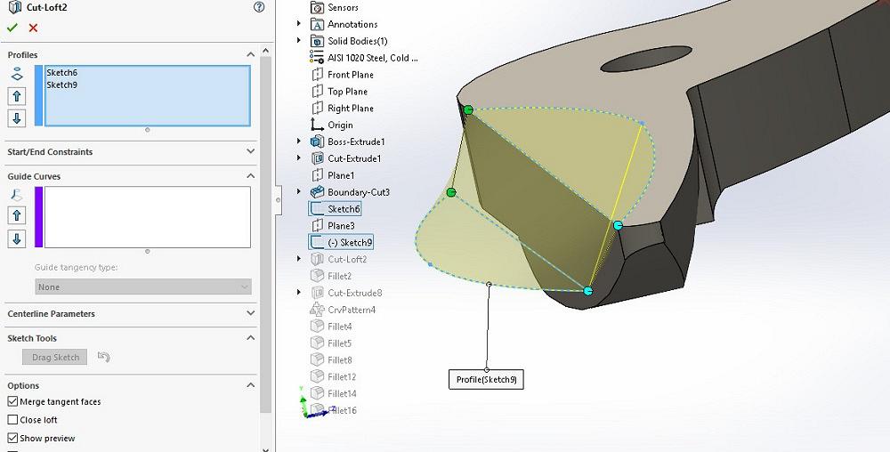
The jaw’s casting has a relief pocket on the cutting side of the blade. To model that, Gunn used a Cut-Loft (see Figure 4). The profiles, as sketched, match the draft of the casting intended for mold release.
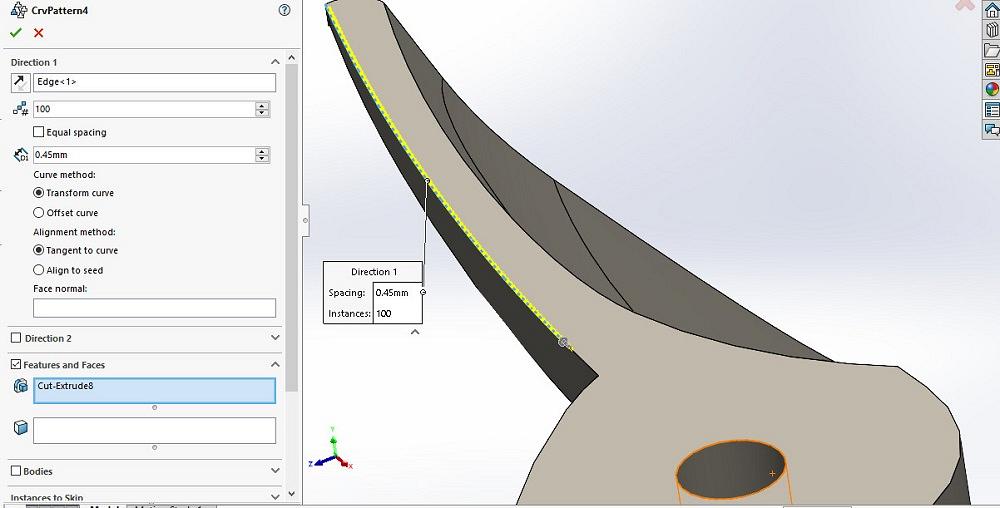
To create the 100 teeth along the serrated edge, a Curve-Driven pattern of a single Cut-Extrude does the job (see Figure 5). A separate sketch could have been used for the curve, but when a curve in a feature is available, skipping the sketch is an efficient technique.
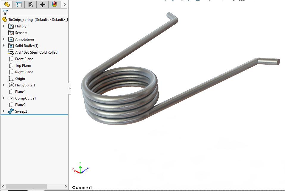
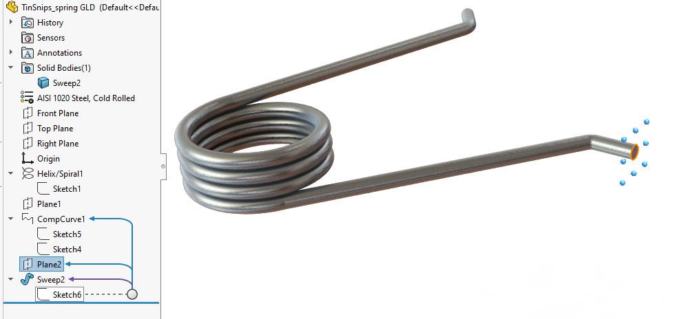
We spring to the topic of a bent wire in Figure 6A. Gunn created a model of a torque spring by sketching a circle and using the Helix-Spiral tool to define a curve for the centerline path of the coil.
The endpoints of that helical curve serve two purposes:
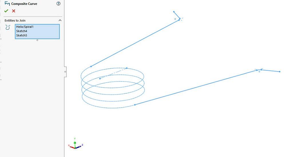
With sketches for the coil and two legs complete, Gunn combined the three into a single curve using the Composite-Curve tool (see Figure 6B). The result is used as a path in an Extruded-Sweep.
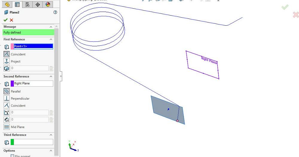
In preparation for sketching the profile of the spring, the right plane was offset to a vertex—an endpoint of the leg sketch (see Figure 6C). A circle was then sketched on that new plane, and with the path and profile sketches complete, the Extruded-Sweep tool was applied. The result is Figure 6A.
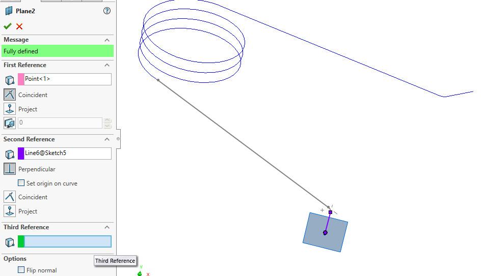
We could embellish Gunn’s work slightly. Note the ends of the spring in Figure 6A. They are nipped off at an angle. That angle is actually parallel to the right plane, not quite “faithful” as the rest of the model.
We edit Mark’s definition of the plane (see Figure 6D) to use a line segment and the end of that segment. The resulting sweep, in Figure 6E, has the ends of the spring perpendicular (i.e., normal) to the centerline of the wire.
I believe the wisdom and effort that goes into CAD modeling should be a legacy offered to peers. Gunn’s CAD technique of nearly a decade ago is still relevant, efficient, and worthy of emulation. The STEP file import workflow is speedy, but it strips away legacy. Huzzah to grabcad.com!


The Fabricator is North America's leading magazine for the metal forming and fabricating industry. The magazine delivers the news, technical articles, and case histories that enable fabricators to do their jobs more efficiently. The Fabricator has served the industry since 1970.
start your free subscription
Easily access valuable industry resources now with full access to the digital edition of The Fabricator.

Easily access valuable industry resources now with full access to the digital edition of The Welder.

Easily access valuable industry resources now with full access to the digital edition of The Tube and Pipe Journal.

Easily access valuable industry resources now with full access to the digital edition of The Fabricator en Español.
In this episode of The Fabricator Podcast, Caleb Chamberlain, co-founder and CEO of OSH Cut, discusses his company’s...


