


Contributing Writer
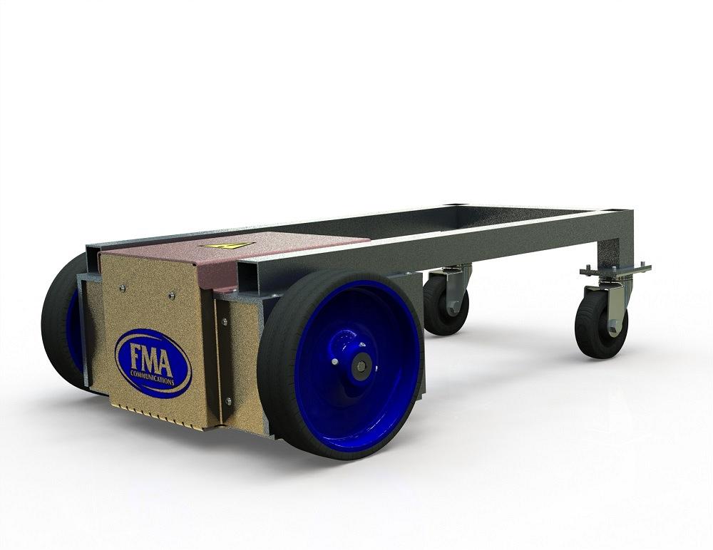
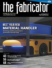
FIGURE 1. Can a JPEG file be used to fabricate? How about a STEP? Who needs PDFs?
When I was working in sales for a sheet metal job shop, customers would ask, “If I send you a JPEG file, can you ship the real deal to me?” An example of such a request is shown in Figure 1—a radio-controlled “smart” cart. I’d usually ask for a STEP file and PDF instead of the JPG file.
Author recommendation: Learn more about the STEP file format and other useful CAD industry trends from Ralph Grabowski’s upfront.eZine newsletter. Issue #111.1 (November 2021) delves into the details and history of the STEP format. Here is a snippet:
“The first release of STEP came out in 1995. Sometimes you also see it referred to as AP203 (short for application protocol level 2). Today, STEP consists of 800 standards ... of which four are for end users, with the remainder a library of reusable definitions: AP203 for solid models (1995), AP214 for assemblies (2003), AP242 for annotations (2015), and AP242e2 for tolerances (2020).”
So, no, a JPEG isn’t enough. Yes, a STEP file is a maybe. There is a world (ASME Y14.41-2019) where a STEP file for an assembly could be converted into actual metal and plastic with little need for 2D drawings. CNC software is getting closer to eliminating the drafting table.
In my little world (ASME 14.5), fully detailed drawings remain part of the fabrication process, mostly for quality control, sometimes to support the labor of CAM.
PDFs and 2D drawings are relied upon to verify that the CNC translation of the STEP went well. The battle over inches and millimeters is a common agony. They are also useful to verify that the part didn’t slip in the clamps, the correct material was used, the correct tooling was loaded for a batch of parts, and the correct finish was achieved. Among their many benefits, PDFs are indelible and instantly human-readable; on the other hand, STEP files don’t mean much to most people. To see what I mean, open one up with Notepad for a peek.
If the project is for a one-off build, receiving inspection and quality control are probably limited to fit and function. If the part adjustment can be made during assembly, it is acceptable. No inspection report needed.
Looking at the other extreme, if the project will span years and will be fabricated in countless batches, verification by accept/reject inspection is the norm. The component is expected to fit perfectly when it arrives on the assembly line. Downtime in assembly is not acceptable.
As a small job shop guy, many of my customers were inventors, not skilled production engineers. They were not aware of STEP files. Preparation of drawings was irrelevant and something they were willing to delegate, often with the assumption that I’d attach the shop drawings I made to the packing list.
I’m writing many of these columns for such newbies to fabrication. ASME Y14.41 is a great way to minimize wasted effort. A note on the drawing might say “See STEP File For Missing Dimensions.” Such drafting standards allow the drawing to just list the few critical dimensions that must be inspected. The important role of the 2D PDF drawing is to specify what the STEP can’t convey, specifics like color, finish, packaging, and tolerances. I’ve recently learned that AP242e2 conveys tolerances, but I have no experience with that … yet.
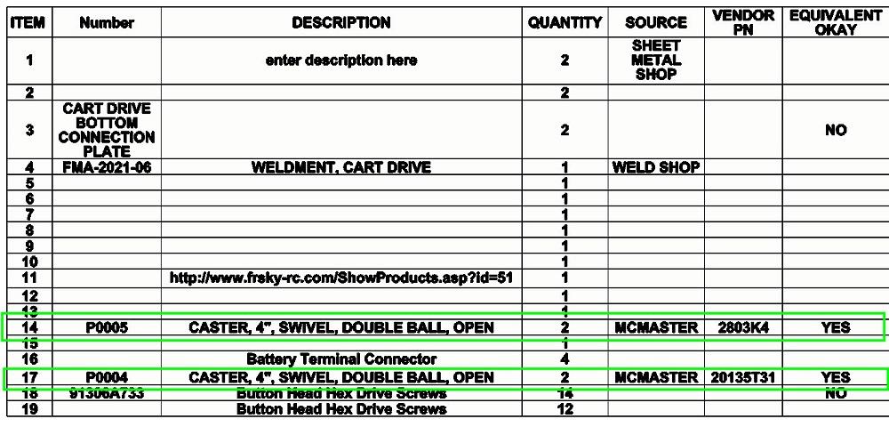
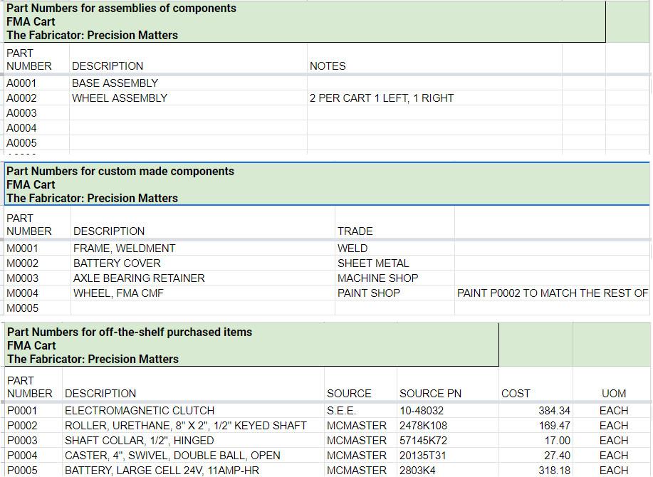
FIGURE 2. The current state of the bill of materials is dismal. Few of the entries have accurate product manufacturing information. Workflow will proceed from item 1 to item 19, correcting the PMI as we go.
The drafting trick (for me) is to know which dimension is critical and must appear on the drawing. From bitter experience, the quickest way to find out is to leave a dimension off the PDF.
Regardless of the degree to which ASME 14.41 is implemented, the CAD jockey is responsible for naming and identifying the required ingredients. Data entry and file naming remain a significant CAD task.
Who employs the CAD jockey to prepare STEP files and drawings is a matter of circumstance. The employer could be a job shop, a customer, or someone contracted by the customer. The grunt work must be accounted for in the project’s budget. To put it another way, this project has transitioned from computer-aided design to computer-aided drafting. Ownership of the resulting intellectual property is a matter of understanding among all parties.
The model used to create the rendering in Figure 1 was also used to create the BOM shown in Figure 2. Being only slightly useful, the mess in Figure 2 is the result of hasty workflow. Some models were downloaded and stuffed into the assembly, and other local files were created with as few mouse-clicks as possible. Little attention was paid to product manufacturing information (PMI)—the part numbers and descriptions.
The CAD jockey’s objective thus far, as demonstrated in preceding episodes, has been to develop a realistic visual prototype quickly. During our previous episode, the visual prototype received approval for documentation.
The messy BOM in Figure 2 becomes a task list. A suggested workflow is to start at the top and work, line-by-line, through the assignment of part numbers, descriptions, and sources. But first …
The cart’s activity log, introduced in the previous episode, is among the first files opened for editing. Figure 3 is a screenshot of the google sheet we’re using to track activity for this project.
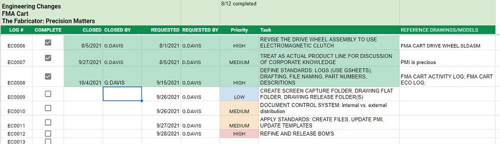
The first activity is to review the engineering change log, shown in Figure 4. EC0009 says we should create a screen capture folder. That folder will retain all of the images created for this project. Windows Explorer is the tool of choice.
A “Drawing History” folder holds all of the PDFs that are created for this project. Copies of every revision will end up here. Those old revisions make restricted access to this folder important. This is an old-style flat file cabinet. Am I dating myself?
The “Drawing Released” folder is the CAD department’s communication path to other departments. The folder only has the current revision that is to be used for fabrication. This folder often contains subfolders that organize the drawings by trade/industry. Examples of such subfolders are Machined, Sheet Metal, Plastic, and Glass. Rather than showing you screenshots of using Windows Explorer, we will declare EC0009 to be complete.
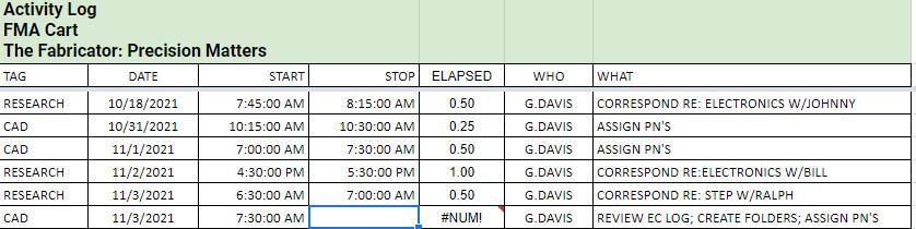
FIGURE 3. We are keeping the activity log for the project updated. It looks like I forgot to sign off before I made this screenshot. Do as I say, not as I do.
EC0010 remains open. Implementing a document control system, also known as the vault, is part of what we’re doing. We’ve punted the decision on what kind of vault to attach to the CAD system. To fundamentally date myself, I grew up on WPDM.
EC0011 (update the PMI) is exactly what we’re working on as we assign part numbers and descriptions.
Figure 5 shows three tabs in the part number spreadsheet—a tab for assemblies, another tab for part to be made, and a third for purchased items. Some progress has been made in data entry in those spreadsheets; now it’s time to make some progress in the CAD.
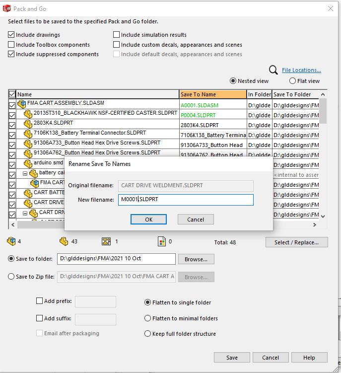
Figure 6 shows progress being made on using Pack and Go to rename CAD files. It was made while assigning M0001.SLDPRT to what had been CART DRIVE WELDMENT.SLDPRT. Every line in the Pack and Go table, as well as every item in our project, will get similar treatment.
If you gaze closely at the first line in the table in Figure 6, you may note (in green) the entry A00001.SLDASM. During the visual prototyping, the CAD file FMA CART ASSEMBLY.sldasm was arbitrarily created out of necessity. Because of our CAD policy of using the file name in the BOM table to show the part number, that assembly has been assigned the file name (and thus part number) A0001.sldasm.
When we meet in the next episode, the Pack and Go operation will be complete. All file names will have been updated. EC0012 will be closed. The BOM in Figure 2 should look more professional. We’ll then turn to creating SLDDRWs, debugging templates, creating more PMI, and completing EC entries.
Here’s a side note on what is realistic and what is real. Reader J.H. saw this project and needed a schematic: “I was wondering if you would be able to direct me to the company building these units, or send me in the correct direction for more information on the electronics side of this cart?”
My reply to J.H. is that this work so far is realistic, not real. I have no schematic, just 3D blobs for mechanical mounting/planning. The models for the Arduino board, RF controller, and other electromechanical devices are downloads to serve as placeholders in the BOM. There are several YouTubers who post how-tos on R2D2-type robots. The difference between the FMA cart and toy robot is merely signal amplification.
It might be fun to have readers contribute parts and schematics to building carts for the industry. If there are proceeds, donate them to FMA.


The Fabricator is North America's leading magazine for the metal forming and fabricating industry. The magazine delivers the news, technical articles, and case histories that enable fabricators to do their jobs more efficiently. The Fabricator has served the industry since 1970.
start your free subscription
Easily access valuable industry resources now with full access to the digital edition of The Fabricator.

Easily access valuable industry resources now with full access to the digital edition of The Welder.

Easily access valuable industry resources now with full access to the digital edition of The Tube and Pipe Journal.

Easily access valuable industry resources now with full access to the digital edition of The Fabricator en Español.
In this episode of The Fabricator Podcast, Caleb Chamberlain, co-founder and CEO of OSH Cut, discusses his company’s...


